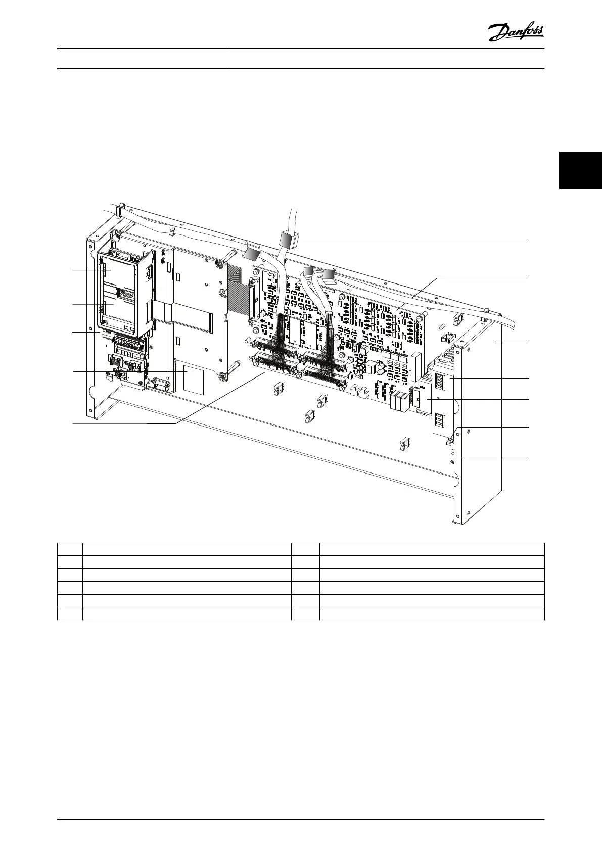
3.6.4 View of Control Shelf
Illustration 3.5 shows a control shelf with cables connecting it to 4 VLT
®
Parallel Drive Modules. The control shelf holds the
LCP, MDCIC, and control terminals. The LCP shows alarm and warning messages and provides access to the system
parameters. The MDCIC is connected to each of the drive modules via a 44-pin ribbon cable, and delivers control signals to
the modules. The control card communicates with the MDCIC via a cable.
1 LCP cradle 7 Multi-drive control interface card (MDCIC)
2 LCP control card (underneath cover) 8 Control shelf
3 Control terminal blocks 9 Power supply for Pilz relay (optional)
4 System identication label 10 Pilz relay (optional)
5 44-pin cables between MDCIC and drive modules 11 DIN rail
6 Ferrite core 12 Drive relay terminals
Illustration 3.5 View of the Control Shelf
Product Overview Service Guide
MG94A502 Danfoss A/S © 02/2019 All rights reserved. 25
3 3
 Loading...


