4.8 Control Terminal Functions
Table 4.13 describes the functions of the control terminals. Many of these terminals have multiple functions determined by
parameter settings. Some options provide more terminals.
Terminal Function
01, 02, 03 and 04, 05, 06 Two Form C output relays. Maximum 240 V AC, 2 A. Minimum 24 V DC, 10 mA, or 24 V AC, 100 mA. Can
be used for indicating status and warnings. Found on the power card.
12, 13 24 V DC supply to digital inputs and external transducers. The maximum output current is 200 mA.
18, 19, 27, 29, 32, 33
Digital inputs for controlling the drive. R = 2 kΩ. Less than 5 V = logic 0 (open). Greater than 10 V = logic
1 (closed). Terminals 27 and 29 are programmable as digital/pulse outputs.
20 Common for digital inputs.
37 0–24 V DC input for Safe Torque O (some units).
39 Common for analog and digital outputs.
42 Analog and digital outputs for indicating values such as frequency, reference, current, and torque. The
analog signal is 0/4 to 20 mA at a maximum of 500 Ω. The digital signal is 24 V DC at a minimum of 500
Ω.
50 10 V DC, 15 mA maximum analog supply voltage for potentiometer or thermistor.
53, 54
Selectable for 0–10 V DC voltage input, R = 10 kΩ, or analog signals 0/4 to 20 mA at a maximum of
200 Ω. Used for reference or feedback signals. A thermistor can be connected here.
55 Common for terminals 53 and 54.
61 RS485 common.
68, 69 RS485 interface and serial communication.
Table 4.13 Control Terminals and Functions
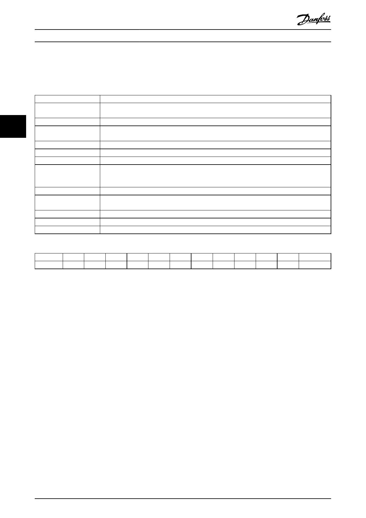
Terminal 18 19 27 29 32 33 37 53 54 42 1–3 4–6
Parameter 5-10 5-11 5-12 5-13 5-14 5-15 5-19 6-1* 6-2* 6-5* 5-4* 5-4*
Table 4.14 Control Terminals and Associated Parameters
Operator Interface and Driv...
VLT
®
FC Series, D1h–D8h, Da2/Db2/Da4/Db4, E1h–E4h, J8/J9
40 Danfoss A/S © 02/2019 All rights reserved. MG94A502
44
 Loading...


