EasyManuals Logo
Home>Danfoss>DC Drives>VLT AutomationDrive FC 300 Series

Danfoss VLT AutomationDrive FC 300 Series Service Guide

Danfoss VLT AutomationDrive FC 300 Series
370 pages
To Next Page IconTo Next Page
To Previous Page IconTo Previous Page
Page #29 background imageLoading...
Page #29 background image
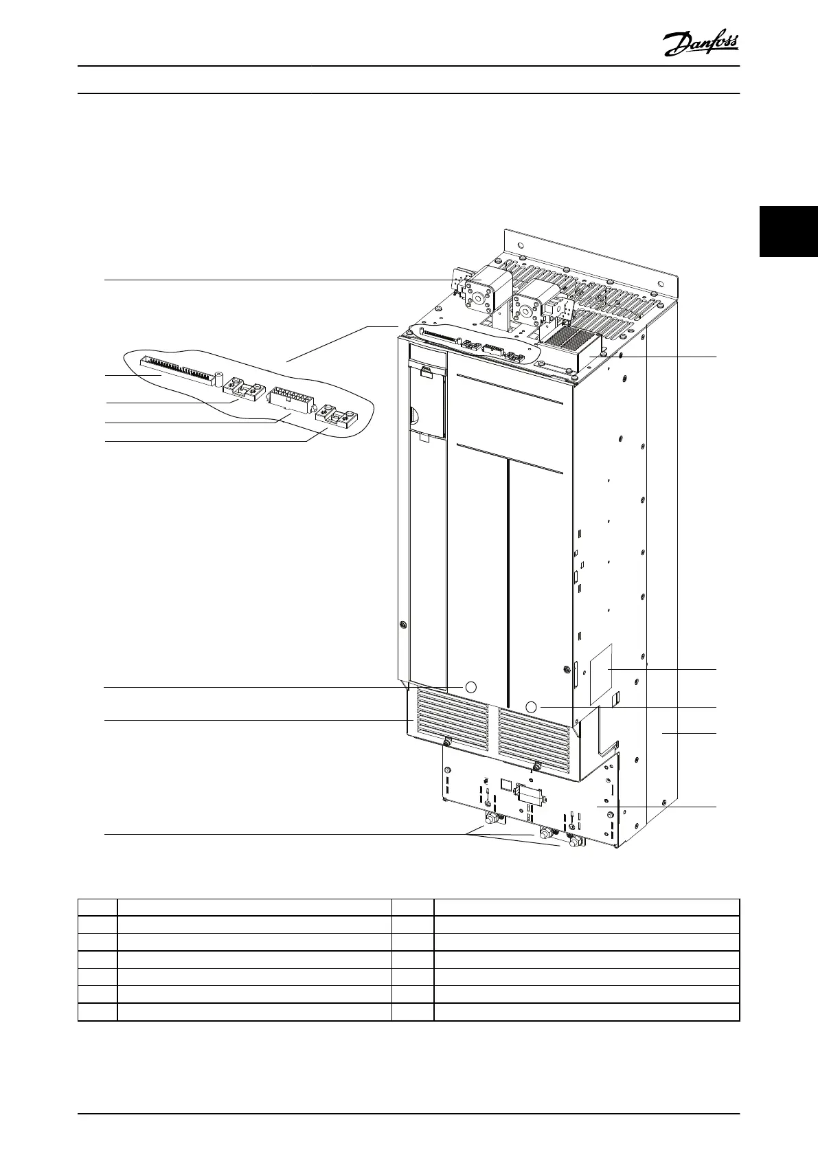
3.6.6 View of Parallel Drive Module
Each drive module has an IP00 protection rating. Either 2 or 4 modules can be connected in parallel to create a drive
system.
130BE561.11
2
3
4
1
5
6
7
8
9
12
13
11
10
1 DC-link terminal and DC fuse 8 Ground terminals
2 MDCIC plug 9 Top fan
3 Microswitch to DC fuse connector 10 Drive module label
4 Relay 1 and 2 connector 11 Motor output terminals (inside the unit)
5 Brake fault jumper and connector 12 Heat sink and heat sink fan
6 Mains input terminals (inside the unit) 13 Ground plate
7 Terminal cover – –
Illustration 3.7 View of Parallel Drive Module
Product Overview Service Guide
MG94A502 Danfoss A/S © 02/2019 All rights reserved. 27
3 3

Table of Contents

Other manuals for Danfoss VLT AutomationDrive FC 300 Series

Questions and Answers:

Question and Answer IconNeed help?

Do you have a question about the Danfoss VLT AutomationDrive FC 300 Series and is the answer not in the manual?

Danfoss VLT AutomationDrive FC 300 Series Specifications

General IconGeneral
BrandDanfoss
ModelVLT AutomationDrive FC 300 Series
CategoryDC Drives
LanguageEnglish

Related product manuals