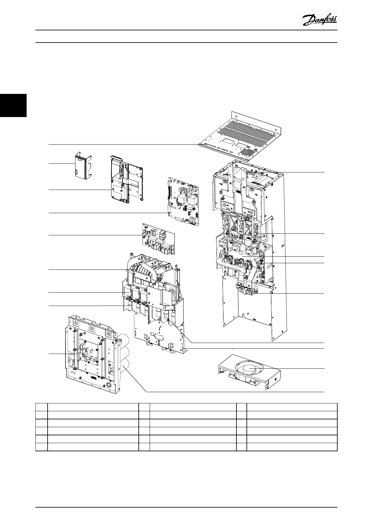
3.6.5 Exploded View of Parallel Drive Module
VLT
®
Parallel Drive Modules are used in parallel drive systems, not as standalone modules. The parallel drive modules do not
hold the control card and LCP, which are mounted on the control shelf. The modules connect to the control shelf via the
cable connectors at the top of each module.
130BF895.10
2
3
4
15
5
8
18
9
11
6
14
12
1
7
10
13
16
17
1 MDCIC cable connector slot 7 AC fuse 13 IGBT modules
2 Blank cover plate (no LCP) 8 Mains input terminal 14 Brake terminals (optional)
3 Mounting plate (no control card) 9 Balance/high frequency card 15 Motor output terminal
4 Power card and mounting plate 10 Busbar/regeneration terminal 16 Power terminal mounting plate
5 Inrush card 11 SCR/diode modules 17 Heat sink fan
6 RFI lter (optional) 12 Gate drive card 18 Capacitor bank
Illustration 3.6 Exploded View of Parallel Drive Module
Product Overview
VLT
®
FC Series, D1h–D8h, Da2/Db2/Da4/Db4, E1h–E4h, J8/J9
26 Danfoss A/S © 02/2019 All rights reserved. MG94A502
33
 Loading...


