2.3 Mechanical Installation
2.3.1 Recommended Tools and Equipment
Equipment Size Description
Screwdrivers
Socket (Hex) 8 For fastening inverter
screws/mounting
of brackets
Slotted 0.4x2.5 For spring loaded power and
control terminals
Slotted/Torx 1.0x5.5/TX20 For cable
clamps inside the
installation box
Spanner 19, 24, 28
For blind-plugs
LCP, part no.
130B1078
Local control panel
LCP cable, part no.
130B5776
Connection cable for local
control
panel
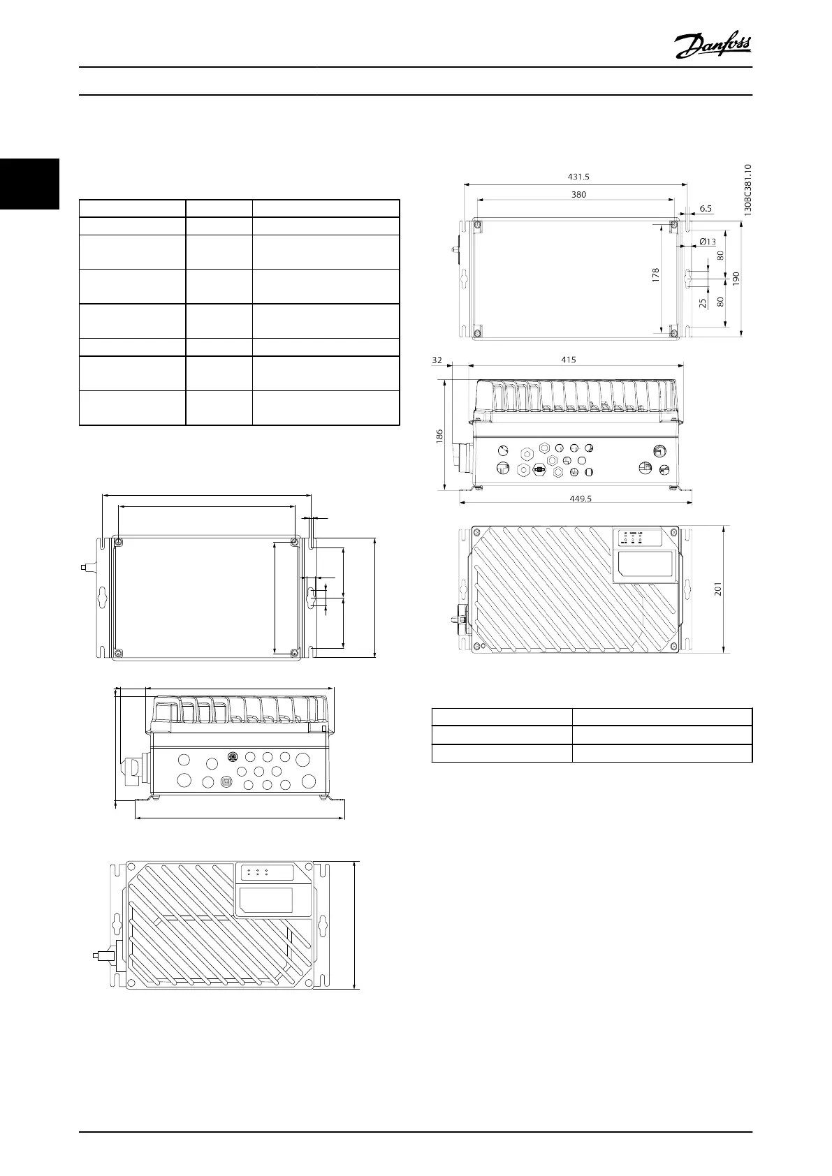
2.3.2 Mechanical Dimensions
41
175
349.5
315
ON
WARNING
ALARM
Bus MS NS2NS1
331.5
280
178
6.5
80
80
190
25
Ø13
130BB712.10
200
1
2
3
4
Illustration 2.3 Cable Entries and Hole Sizes (Small Unit)
Illustration 2.4 Cable Entries and Hole Sizes (Large Unit)
Motor side 1xM20, 1xM25
Control side
2xM20, 9xM16
1)
Mains side 2xM25
1)
Also used for
4xM12/6xM12 sensor/acuator sockets.
2.3.3 Cooling
The FCD 302 has no forced cooling. It relies only on
natural convection for cooling
using the cooling fins.
•
A minimum of 100 mm (4 in) top and bottom air
cooling clearance must be provided. See
Illustration 2.5.
•
Derating starts above 40°C (104°F) and 1000 m
(3300 ft) elevation above sea level. See FCD 302
Design Guide, MG04HXYY for detailed information.
Installation
VLT
®
Decentral Drive FCD 302 Operating Instructions
12 MG04F302 - VLT
®
is a registered Danfoss trademark
22
Phone: 800.894.0412 - Fax: 888.723.4773 - Web: www.clrwtr.com - Email: info@clrwtr.com

 Loading...


