1.4 Additional Resources
Other resources are available to understand advanced
frequency controller functions and programming.
•
The FCD 302 Programming Guide, MG04GXYY,
provides greater detail in how to work with
parameters and many application examples.
•
The FCD 302 Design Guide, MG04HXYY, is intended
to provide detailed capabilities and functionality
to design motor control systems.
•
MCB 102 manual
•
MCB 103 manual
•
Safe PLC Interface Option MCB 108 instruction,
MI33JXYY
.
•
Fieldbus manuals: Profibus manual
MG34NXYY,
Ethernet manual MG90JXYY, and ProfiNet manual
MG90UXYY.
•
Brake Resistor Design Guide MG90OXYY
•
Training courses both on-line and in person.
•
Hotline, telephone and on-line help.
•
Installation, set up, and commissioning is also
available by Danfoss trained and approved
installers.
•
Danfoss sales representatives are also trained to
provide customer service and instruction for
applications.
Contact your Danfoss supplier or go to Danfoss website
for downloads or additional information. In technical
literature reference numbers, X refers to version number
and YY refers to language code.
1.5 Product Overview
A frequency converter is an electronic motor controller
that converts AC mains input into a variable AC waveform
output. The frequency and voltage of the output are
regulated to control the motor speed or torque.
In addition, the frequency converter monitors the system
and motor status, issues warnings or alarms for fault
conditions, starts and stops the motor, optimizes energy
efficiency, provides line harmonics protection, and offers
many more control, monitoring, and efficiency functions.
Operation and monitoring functions are available as status
indications to an outside control system or serial communi-
cation network.
The FCD 302 is designed for decentral mounting, for
example, in the food and beverage industry, or for other
material handling applications. With the FCD 302 it is
possible to reduce costs by placing the power electronics
decentrally. Central panels are then rendered obsolete,
saving cost, space and effort for installation and wiring.
The basic design is service-friendly, with a pluggable
electronic part and a flexible and “spacious” wiring box. It
is easy to change electronics without the need for re-
wiring.
1.6 Internal Frequency Converter Controller
Functions
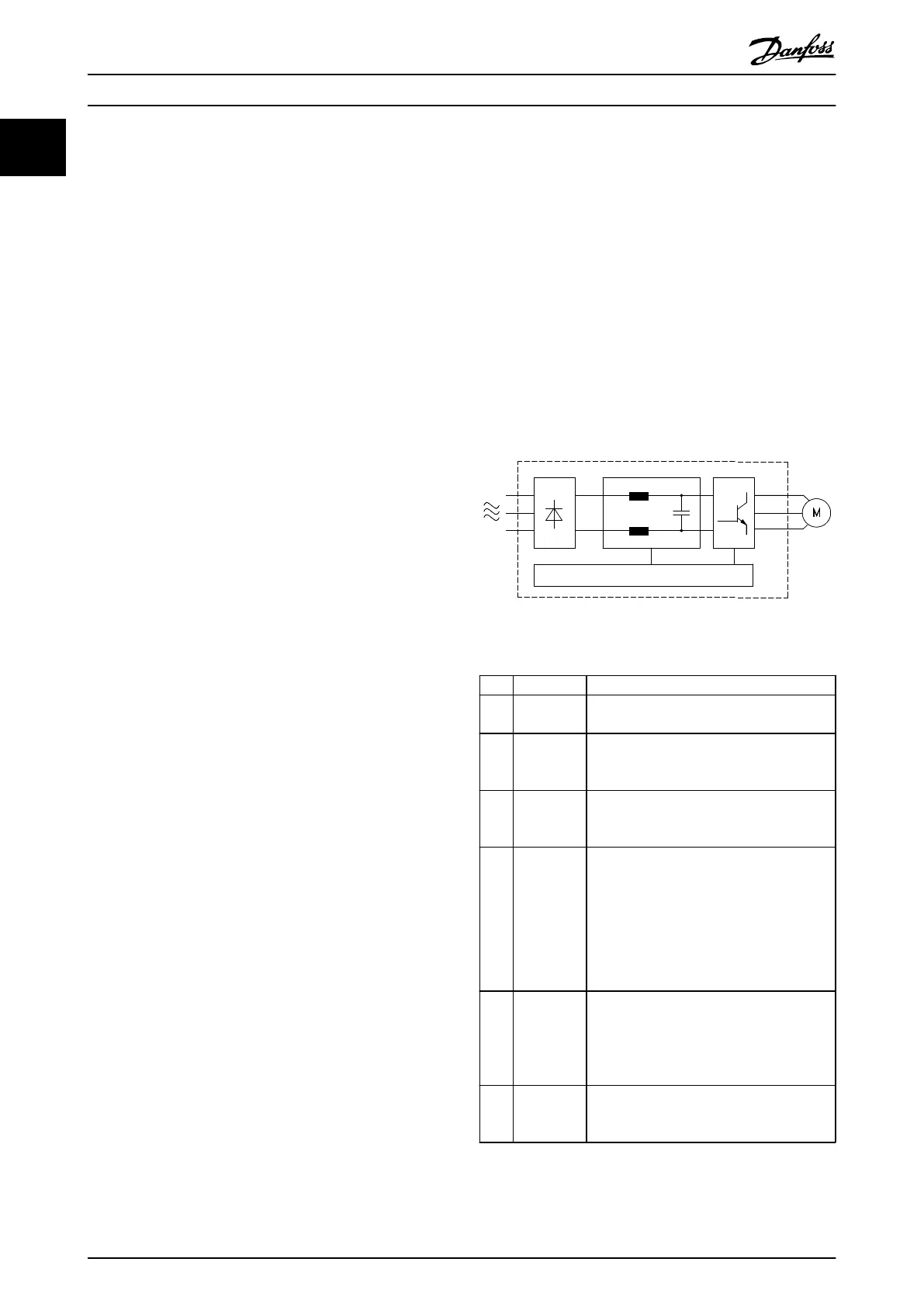
Below is a block diagram of the internal components of
the frequency converter. See Table 1.1 for their functions.
Illustration 1.1 Frequency Converter Block Diagram
Area Title Functions
1 Mains input Three-phase AC mains power supply to the
frequency
converter.
2 Rectifier The rectifier
bridge converts the AC input to
DC current for use
within the frequency
converter.
3 DC bus The intermediate DC-bus circuit of the
frequency converter handles the
DC current
for internal routing.
4 DC line
reactors
•
Filter the intermediate DC
circuit voltage
•
Prove line transient protection
•
Reduce RMS current
•
Raise the power factor reflected back to
the line
•
Reduce harmonics on the AC input
5 Capacitor
bank
•
Stores the DC power
•
Provides
a regulated DC current supply
•
Provides ride-through protection for
short power losses
6 Inverter The inverter converts the DC into a
controlled PWM AC waveform
for a
controlled variable output to the motor.
Introduction
VLT
®
Decentral Drive FCD 302 Operating Instructions
6 MG04F302 - VLT
®
is a registered Danfoss trademark
11
Phone: 800.894.0412 - Fax: 888.723.4773 - Web: www.clrwtr.com - Email: info@clrwtr.com

 Loading...


