100 (4)
100 (4)
100 (4)
100 (4)
195NA261.10
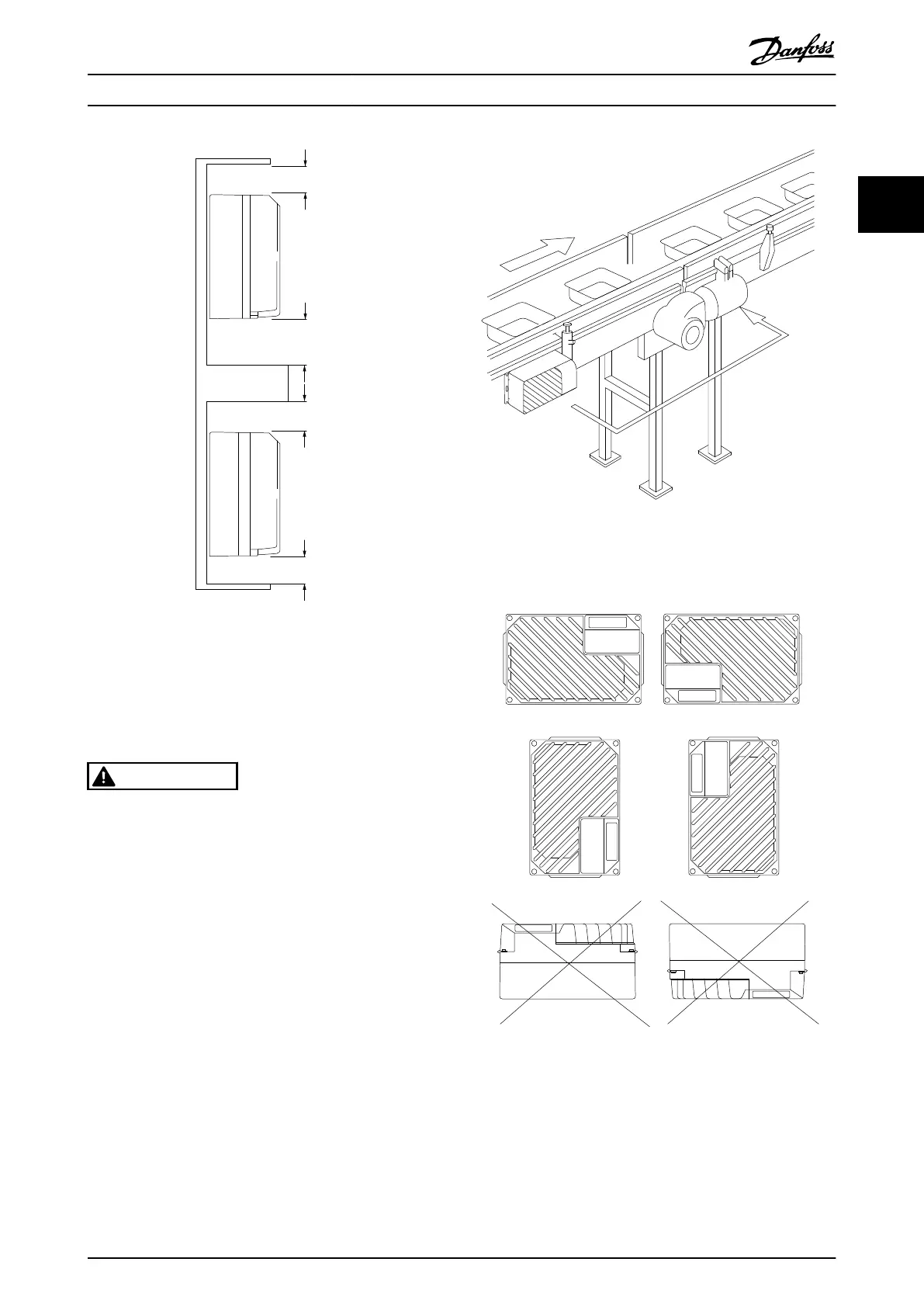
Illustration 2.5 Top and Bottom Cooling Clearance
2.3.4 Mounting
The FCD 302 consists of two parts: The installation box and
the
electronic
part.
See
2.2 Exploded View of the FCD 302.
WARNING
Do not switch on the mains before the 4 screws are
tightened. Failure to tighten
these screws can result in
personal injury or material damage when the unit is
loaded.
Stand alone mounting
•
The holes on the
rear of the installation box are
used to fix mounting brackets
•
Ensure that the strength of the mounting location
can support the unit weight
•
Make sure that the proper mounting screws or
bolts are used
Illustration 2.6 FCD 302 Stand Alone Mounted with Mounting
Brackets
Permitted mounting positions
Illustration 2.7 Permitted Mounting Positions - Standard
Applications
Installation
VLT
®
Decentral Drive FCD 302 Operating Instructions
MG04F302 - VLT
®
is a registered Danfoss trademark
13
2 2
Phone: 800.894.0412 - Fax: 888.723.4773 - Web: www.clrwtr.com - Email: info@clrwtr.com

 Loading...


