130BC286.10
U
96
V
97
W
98
L1
L2
L3
L1
91
L2
92
L3
93
12
27
T1
T2
T3
NO
NC
NO
NC
L2
L3
PE
L1
41
33
5
3
1 2
4
6
34
42
1
2
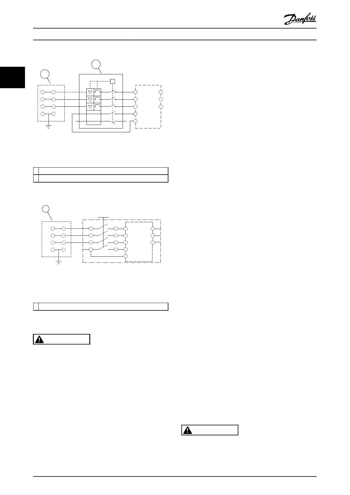
Illustration 2.10 Large Unit only: Circuit Breaker and Mains
Disconnect
1 Looping terminals
2 Circuit breaker
L1
L2
L3
PE
U
96
V
97
W
98
L1
91
L2
92
L3
93
12
27
U
V
W
1 2
3 4
5
6
7 8
1
130BC287.10
Illustration 2.11 Large Unit only: Service Switch at Mains with
Looping Terminals
1 Looping terminals
2.4.1 Requirements
WARNING
EQUIPMENT HAZARD
Rotating shafts and electrical
equipment can be hazardous.
All electrical work must conform to national and local
electrical codes. Installation, start-up, and maintenance to
be performed only by trained and qualified personnel.
Failure to follow these guidelines could result in death or
serious injury.
For your safety, comply with the following requirements:
•
Electronic controls equipment is
connected to
hazardous mains voltage. Take extreme
precautions against electrical hazards when
applying power to the unit.
•
Wear safety glasses whenever working on electric
control or rotating equipment.
•
Run motor cables from
multiple frequency
converters separately. Induced voltage from
output motor cables run together can charge
equipment capacitors even with the equipment
turned off and locked out.
Overload and equipment protection
•
An electronically activated function within the
frequency converter provides overload protection
for the motor. Set 1-90 Motor Thermal Protection
to warning or trip as required. Refer to the FCD
302 Programming Guide MG04GXYY for further
information. 1-90 Motor Thermal Protection
measures motor current and is internally set
based on the value in 1-24 Motor Current. A 1.2 x
FLA (full load amps) service factor is built in and
maintained. Should the motor current increase
above that value, the overload calculates the
level of increase to activate timing for the trip
(controller output stop) function. The higher the
current draw, the quicker the trip response. The
overload provides Class 20 motor protection. See
7 Troubleshooting for details on the trip function.
•
Because the motor wiring carries high frequency
current, it is important that wiring for mains input
power, motor power, and control are run
separately. Use separated shielded wire or
metallic conduit. Failure to isolate power, motor,
and control wiring could result in less than
optimum equipment performance.
•
When using cable trays, place sensitive cables
such as telephone or data cables in a separate
cable tray to the motor cable. If signal cables run
across power cables, these cables must cross at
an angle of 90°.
Wire type and ratings
•
All wiring must comply with local and national
regulations regarding cross-section and ambient
temperature requirements.
•
The screen must have low RF impedance, which
is achieved by a braided screen of copper,
aluminium or iron.
•
Danfoss recommends that all power connections
are made with a minimum 75°C rated copper
wire.
•
See 8.1 Electrical Data and Wire Sizes for
recommended wire sizes.
Cable glands
It must be assured that appropriate cable glands needed
for the environment are chosen and carefully mounted.
WARNING
Do not plug/unplug the electronic part with mains voltage
switched on.
Installation
VLT
®
Decentral Drive FCD 302 Operating Instructions
16 MG04F302 - VLT
®
is a registered Danfoss trademark
22
Phone: 800.894.0412 - Fax: 888.723.4773 - Web: www.clrwtr.com - Email: info@clrwtr.com

 Loading...


