1. Use a wire stripper to remove the insulation for
proper
grounding.
2.
Secure
the
grounding clamp to the stripped
portion of the wire with the screws provided.
3. Secure the grounding wire to the grounding
clamp provided.
Leakage current (3.5 mA)
NOTE
Follow national and local codes regarding protective
earthing of equipment with a leakage current > 3.5 mA.
The frequency converter technology implies high
frequency switching at high
power. This generates a
leakage current in the earth connection. RFI filtering and
screened motor cables contribute to this phenomenon.
According to EN/IEC61800-5-1 (Power Drive System
Product Standard) which implies special means if the
leakage current exceeds 3.5 mA, earth grounding must be
reinforced in one of the following ways:
•
Earth ground wire, 10 mm
2
(optional accessory
required for mounting, part no. 130B5974).
•
Two separate earth ground wires both complying
with the dimensioning rules.
RCD use
A fault current in the frequency converter or at the output
power terminals can contain a DC component, and
charging of the filter capacitors can cause a transient earth
current. Where Residual Current Devices (RCDs), also
known as Earth Leakage Circuit Breakers (ELCBs), are used,
the following must be taken into account:
•
Use RCDs of type B only
•
Use RCDs with an inrush delay
•
Use RCDs of 300 mA, if possible
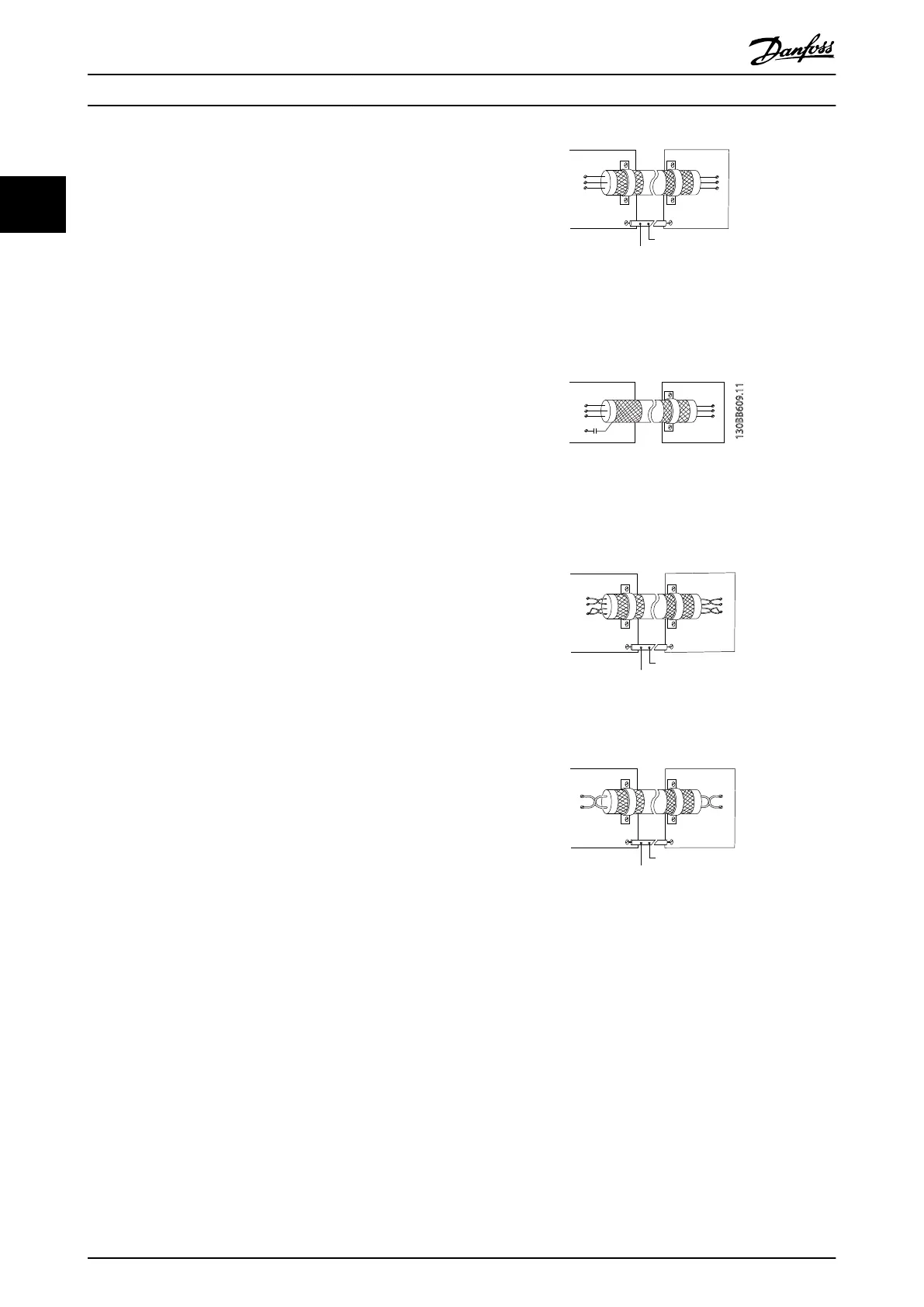
2.4.12 Earthing of Screened Control Cables
Correct screening
The preferred method in most cases is to secure control
and serial communication cables with screening clamps
provided at both ends to ensure best possible high
frequency cable contact.
If the earth potential between the frequency converter and
the PLC is different, electric noise may occur that will
disturb the entire system. Solve this problem by fitting an
equalizing cable next to the control cable. Minimum cable
cross section: 16 mm
2
.
Min. 16 mm²
PE
FC
PE
PLC
130BB922.10
PE PE
- Equalizing cable
50/60 Hz ground loops
With very long control
cables, ground loops may occur. To
eliminate ground loops, connect one end of the screen-to-
ground with a 100nF capacitor (keeping leads short).
100nF
FC
PE
PE
PLC
130BB609.11
Avoid EMC noise on serial communication
This terminal is connected
to earth via an internal RC link.
Use twisted-pair cables to reduce interference between
conductors. The recommended method is shown below:
Min. 16 mm²
PE
FC
PE
FC
130BB923.10
PE PE
- Equalizing cable
69
68
61
69
68
61
Alternatively, the connection to terminal 61 can be
omitted:
Min. 16 mm²
PE
FC
PE
FC
130BB924.10
PE PE
- Equalizing cable
69
69
68
68
2.4.13 DIP Switches
•
Analog input terminals 53
and 54 can select for
either voltage (0-10 V) or current (0-20 mA) input
signals
•
Set switches S201 (terminal 53) and S202
(terminal 54) to select the signal type. ON is for
current, OFF for voltage
•
Terminal 53 default is for a speed reference in
open loop
•
Terminal 54 default is for a feedback signal in
closed loop
Installation
VLT
®
Decentral Drive FCD 302 Operating Instructions
24 MG04F302 - VLT
®
is a registered Danfoss trademark
22
Phone: 800.894.0412 - Fax: 888.723.4773 - Web: www.clrwtr.com - Email: info@clrwtr.com

 Loading...


