For both small and large unit, the service switch is
optional.
The
switch
is
shown mounted on the motor side.
Alternatively, the switch can be located on the mains side,
or omitted.
For the large unit, the circuit breaker is optional. The large
unit can be configured with either service switch or circuit
breaker, not both. The illustration shown is not config-
urable in practice, but is displayed to show the respective
positions of components only.
2.4.3 Terminal Types
Motor, control, and mains terminals are spring loaded
(CAGE-CLAMP)
type.
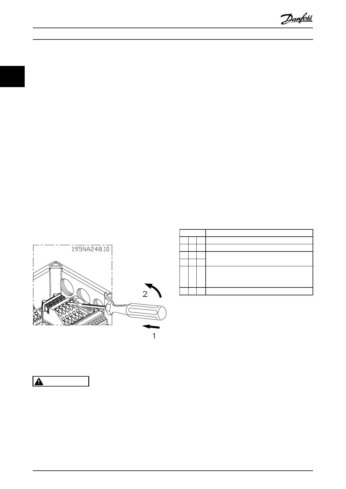
1. Open the contact
by inserting a small screwdriver
into the slot above the contact, as shown in
Illustration 2.14.
2. Insert the stripped wire into the contact.
3. Remove the screwdriver to fasten the wire into
the contact.
4. Ensure that the contact is firmly established and
not loose. Loose wiring can result in equipment
faults or injury.
Illustration 2.14 Opening the Terminals
2.4.4 Motor Connection
WARNING
INDUCED VOLTAGE
Run output motor cables
from multiple frequency
converters separately. Induced voltage from output motor
cables run together can charge equipment capacitors even
with the equipment turned off and locked out. Failure to
run output motor cables separately could result in death
or serious injury.
CAUTION
WIRING ISOLATION
Run input power,
motor wiring, and control wiring in three
separate metallic conduits. Alternatively, use separated
shielded motor and control cables for high frequency noise
isolation. Failure to isolate power, motor and control wiring
can result in sub-optimal performance of the frequency
converter and associated equipment.
MOTOR PROTECTION
Protection against motor overload is not included in the
factory setting. If this function is desired, set 1-90 Motor
Thermal Protection to trip or warning. Refer to the FCD 302
Programming Guide, MG04GXYY for further information.
•
Connect the motor to terminals 96, 97, 98.
•
Connect earth to PE-terminal.
•
Make sure that the screen of the motor cable is
properly earthed at both ends (motor and
frequency converter).
•
For correct dimensioning of cable cross-section,
see 8.1.1 Electrical Data and Wire Sizes.
No.
96 97 98 Motor voltage 0-100% of mains voltage
U V W 3 wires out of motor
U1 V1 W1
6 wires out of motor
W2 U2 V2
U1 V1 W1 6 wires out of motor, Star connected
Connect
U2, V2, W2
separately (optional terminal
block)
PE Earth connection
NOTE
Do not install power
factor correction capacitors between
the frequency converter and the motor.
Do not wire a starting or pole-changing device between
the frequency converter and the motor.
Parallel connection of motors
The frequency converter can
control several parallel-
connected motors. The total current consumption of the
motors must not exceed the rated output current I
M,N
for
the frequency converter.
Installation
VLT
®
Decentral Drive FCD 302 Operating Instructions
18 MG04F302 - VLT
®
is a registered Danfoss trademark
22
Phone: 800.894.0412 - Fax: 888.723.4773 - Web: www.clrwtr.com - Email: info@clrwtr.com

 Loading...


