In hoisting/lowering applications, control of electro-
mechanical
brake
is
required:
•
The
brake is controlled using the special
mechanical brake control/supply terminals 122
and 123.
•
Select [32] Mechanical brake control in parameter
group 5-4*, [1] Array, Relay 2 for applications with
an electro-mechanical brake.
•
The brake is released when the motor current
exceeds the preset value in 2-20 Release Brake
Current.
•
The brake is engaged when the output frequency
is less than the frequency set in 2-21 Activate
Brake Speed [RPM] or 2-22 Activate Brake Speed
[Hz]. The brake engages only when the frequency
converter performs a stop command.
When the frequency converter enters alarm mode or is
exposed to an over-voltage situation, the mechanical brake
immediately cuts in. For more detailed information, refer to
the FCD 302 Programming Guide, MG04GXYY.
NOTE
When
the Mechanical Brake
Control/Supply terminals 122
and 123 are set through parameter group 5-4*, [1] Array,
Relay 2, only one relay output (Relay 1) is available for free
programming.
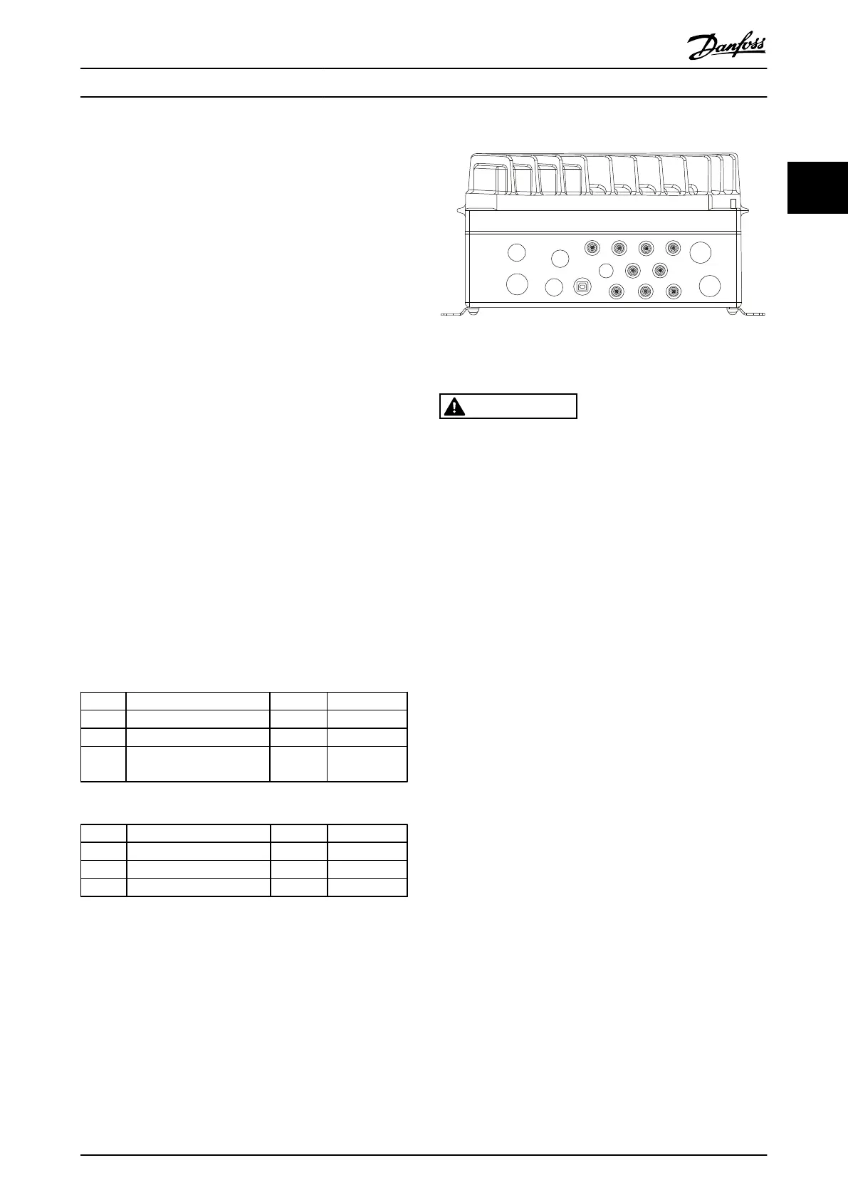
2.4.10 Connection of Sensors/Actuators on
M12
Sockets
Pin Wire colour Terminal Function
1 Brown 12
+24 V
3 Blue 20 0 V
4 Black 18, 19, 32,
33
Digital input
Table 2.1 4xM12 Connection Input
Pin Wire colour Terminal Function
1 Brown Reserved* Reserved
3 Blue 20 0 V
4 Black 02, 05 N.O. (24 V)
Table 2.2 2xM12 Connection Output
* When reserved wires
for option are used. If not utilised, they can be
cut off.
130BC389.10
1
2
3
4
1
2
3
4
1
2
3
4
1
2
3
4
1
2
3
4
1
2
3
4
1
2
3
4
LCP
RL2
RL1
33
USB
3219
FB2 FB1
18
1
2
3
4
1
2
3
4
2.4.11 Earth (Grounding) Requirements
WARNING
GROUNDING HAZARD
For operator safety, it
is important to ground frequency
converter properly in accordance with national and local
electrical codes as well as instructions contained within
this manual. Ground currents are higher than 3.5 mA.
Failure to ground frequency converter properly could
result in death or serious injury.
NOTE
It is the responsibility
of the user or certified electrical
installer to ensure correct grounding (earthing) of the
equipment in accordance with national and local electrical
codes and standards.
•
Proper
protective grounding for
equipment with
ground currents higher than 3.5 mA must be
established, see Leakage Current (3.5 mA)
following.
•
A dedicated ground wire is required for input
power and motor.
•
Use the clamps provided with on the equipment
for proper ground connections.
•
Use of high-strand wire to reduce electrical noise
is recommended.
Installation
VLT
®
Decentral Drive FCD 302 Operating Instructions
MG04F302 - VLT
®
is a registered Danfoss trademark
21
2 2
Phone: 800.894.0412 - Fax: 888.723.4773 - Web: www.clrwtr.com - Email: info@clrwtr.com

 Loading...


