NOTE
•
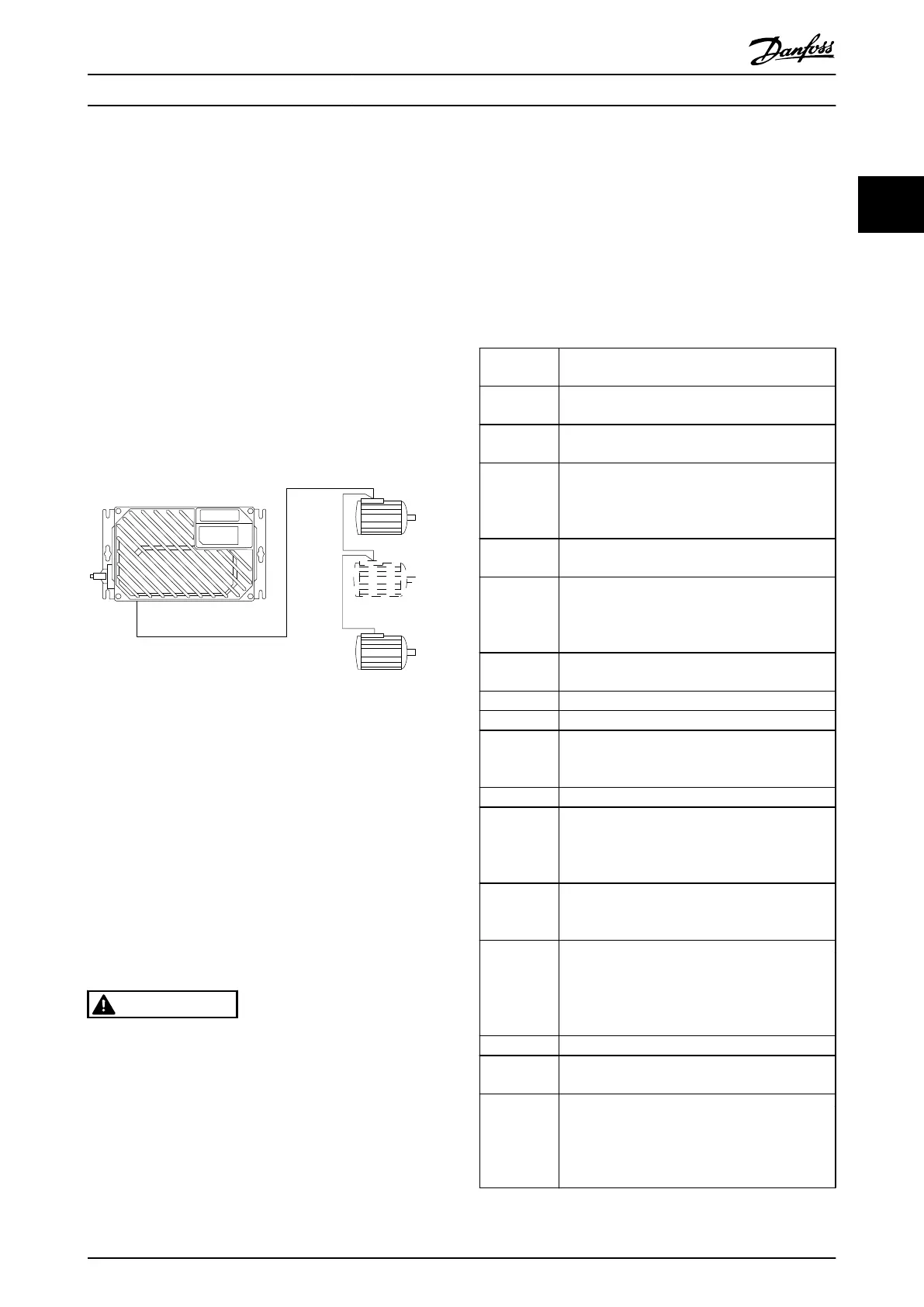
Installations
with
cables
connected
in a common
joint as in Illustration 2.15, is only recommended
for short cable lengths (max. 10 m).
•
When motors are connected in parallel,
1-29 Automatic Motor Adaptation (AMA) cannot be
used.
CAUTION
The electronic thermal relay
(ETR) of the frequency
converter cannot be used as motor protection for the
individual motor in systems with parallel-connected
motors. Provide further motor protection by thermistors in
each motor or individual thermal relays. Circuit breakers
are not suitable as protection.
Illustration 2.15 Parallel Connection of Motors
Problems can arise at start-up and at low RPM values,
when motor sizes differ
widely. Motors of low rated motor
power have a relatively high ohmic resistance in the stator.
This high resistance calls for a higher voltage at start and
at low RPM values. To resolve such a problem:
•
reduce the load during startup, on the motor of
lowest rated motor power
•
configure parallel connections only between
motors of comparable rated motor power
2.4.5 Control Wiring
WARNING
UNINTENDED START
When frequency converter is
connected to AC mains input
power, the motor can start at any time. The frequency
converter, motor, and any driven equipment must be in
operational readiness. Failure to be in operational
readiness when the frequency converter is connected to
AC mains could result in death, serious injury, equipment,
or property damage.
•
It is recommended that
control wiring is rated for
600 V.
•
Isolate control wiring from high-power
components in the frequency converter.
•
If the frequency converter is connected to a
thermistor, for PELV isolation, ensure control
wiring is reinforced/double insulated.
•
See 8.2 General Specifications for control terminal
wiring sizes and maximum loads.
Terminal
No.
Function
01, 02, 03 Relay 1 output. Useable for AC or DC voltage and
resistive or inductive loads.
04,
05, 06 Relay 2 output. Useable for AC or DC voltage and
resistive or inductive loads.
12,
13 24 V DC digital supply voltage. Useable for digital
inputs and external transducers.
To use the 24 V
DC for digital input common, programme
5-00 Digital I/O Mode for PNP operation.
18, 19, 32, 33 Digital inputs. Selectable for NPN or PNP function
in 5-00 Digital I/O
Mode. Default is PNP.
27, 29 Digital inputs or outputs. Programmable for either
5-01 Terminal 27 Mode
for terminal 27 and
5-02 Terminal 29 Mode for 29 selects input/output
function. Default setting is input.
35 Common (-) for external 24 V control back up
supply. Optional.
36 External + 24
V control back up supply. Optional.
37 Safe Stop. See Safe Stop installation for details.
20 Common for digital inputs. To use for digital
input
common, programme 5-00 Digital I/O Mode
for NPN operation.
39 Common for analog output.
42 Analog output. Programmable for various
functions
in parameter group
6-5*. The analog
signal is 0-20 mA or 4-20 mA at a maximum of
500 Ω.
50 10 V DC analog supply voltage. 15 mA maximum
commonly used for a
potentiometer or
thermistor.
53, 54
Analog input. Selectable for voltage (0 to ±10 V)
or current (0- or 4 to ±20 mA). Closed is for
current and open is for voltage. Switches are
located on the frequency converter control card.
See 2.4.13 DIP Switches
55 Common for analog inputs.
61 Common for serial communication (RS-485
interface). See 2.4.13 DIP
Switches
68 (+), 69 (-) RS-485 interface. When the frequency converter is
connected to an RS-485
serial communication
bus, a switch on thecontrol card is provided for
termination resistance. Set the switch to ON for
termination and OFF for no termination.
Installation
VLT
®
Decentral Drive FCD 302 Operating Instructions
MG04F302 - VLT
®
is a registered Danfoss trademark
19
2 2
Phone: 800.894.0412 - Fax: 888.723.4773 - Web: www.clrwtr.com - Email: info@clrwtr.com

 Loading...


