Dell
PowerEdge R510 Technical Guide 18
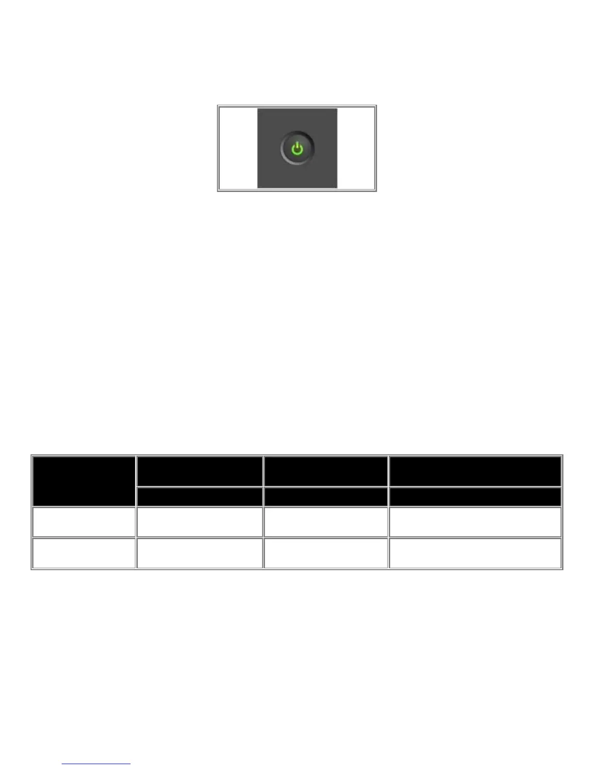
4.3.3 Power Button/Power LED
The power button controls the system's power, turning the unit on and off. All PowerEdge servers have the
power LED light-pipe integrated in the power button. The LED is a green standard Power icon.
Figure 6. Power Button/LED Implementation
The Power LED has two states:
• Power LED is OFF: System is not operating, regardless of AC present. (Other AUX powered
subsystems may be operational with AC power present.)
• Power LED is ON (Green): System is operating. One or more of the non-standby (Vaux) power rails are
active.
All PowerEdge servers include a green colored LED on the motherboard to indicate the presence of standby
power (Vaux). This LED is in a visible location for service personnel. Some server operating systems allow
users to configure the function of the power button through the ACPI feature.
The system has the capability to remember the state of the Power button prior to AC loss (option selected
through BIOS setup). If this option is enabled via BIOS setup, system power returns to the state prior to AC
loss with the resumption of AC.
If the power button is disabled through system management mechanisms, the user can shut down the system
during a crash (regardless of the Power button enable/disable settings).
Table 6. Power Button Behavior under ACPI/Non-ACPI Operating Systems
Action
ACPI OS w/ACPI Enabled
w/ ACPI Disabled ACPI or Non-ACPI OS
power button
System performs a graceful
shutdown
6 seconds
System starts and shuts down 6
seconds later.
4.3.4 Video Connector (Rack Systems)
The video connector is used to attach a video graphics array (VGA)-compatible monitor to rack-based
systems. Space around the connector accommodates full usage of it with all adjacent interfaces (USB
connectors, button, LED’s, etc.).
4.3.5 USB Connectors
USB connectors are used to attach USB-compliant devices such as keyboards, mice, storage keys, and
peripherals to the system. All PowerEdge systems have at least 2 front-accessible USB 2.0 compliant ports

 Loading...