Dell
PowerEdge R510 Technical Guide 19
spaced to accommodate full usage of both connectors simultaneously with other front panel features (e.g.,
Video connector, buttons, LEDs) without mechanical interference. These ports must be connected to the same
controller and cannot be shared with internal or back USB ports.
For security, all external USB ports have an enable/disable function. Internal USB ports connected to internal
persistent storage devices have an enable/disable function independent of the other ports in the system.
Except for platforms using chipsets that allow independent control to enable/disable each USB controller,
disabling USB controllers observe the hierarchy detailed in Table 7 (listed from lowest to highest priority in a 3-
controller design).
Table 7. USB Controller Priorities
No other controller is disabled
Controller 3 is disabled as well
Controllers 2 & 3 are disabled as well
This hierarchy dictates that connections that are lower in the hierarchy be disabled anytime a higher level
connection is disabled.
4.3.6 DVD/CD
If present, the DVD/CD drive has an eject mechanism and a green activity LED. The eject mechanism is
functional with or without power.
4.3.7 Hard Drive Activity LED
The PowerEdge R510 systems have a single (common) green hard drive activity LED that lights when the
system is accessing data on the drive. These systems do not have Status LEDs.
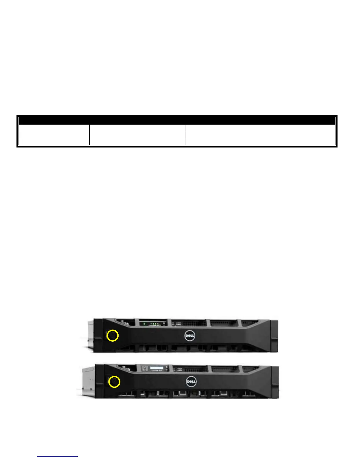
4.3.8 Key Lock
All PowerEdge servers have key locks on their front bezels to prevent access to the systems resources.
There is a single key lock implementation with a single key code across all PowerEdge™ tower and rack
servers.
Key orientation is as follows: Vertical (12 o'clock) position is unlocked. Right (3 o'clock) position is locked.
For rack systems, the bezel locks all front panel access.
Figure 7. Bezel Lock on Front Access Panel

 Loading...