TP70P-211LC1T/TP04P-20EXL1T Operation Manual
3-10
(2) Reading channel input values
Read the input values (16-bit) from the corresponding channels; the maximum allowable number to be read is 32000.
As the example shown above IO1 outputs the value to CH1. The output value of IO1 should be close to the input
value of CH1.
When setting the mode of CH2 to 1, it is 0 ~ 10 V, and if there is no input voltage, the input value should be close to 0.
Analog current outputs
(1) Setting up the channel mode
Channel Mode
0 (default) 1
Description
4 ~ 20 mA 0 ~ 20 mA
(2) Setting up the value to output
The value to output should be in the range of 0 to 32000 for each channel. The value 0 corresponds to the minimum
value of the mode set and the value 32000 corresponds to the maximum value of the mode set. See the following
examples for reference.
IO1: set the mode to 1, it is 0 ~ 20 mA and when the output value is 8000, the output current is 5 mA.
IO2: set the mode to 1, it is 0 ~ 20 mA and when the output value is 16000, the output current is 10 mA.
IO3: set the mode to 0, it is 4 ~ 20 mA and when the output value is 8000, the output current is 8 mA.
IO4: set the mode to 0, it is 4 ~ 20 mA and when the output value is 16000, the output current is 12 mA.
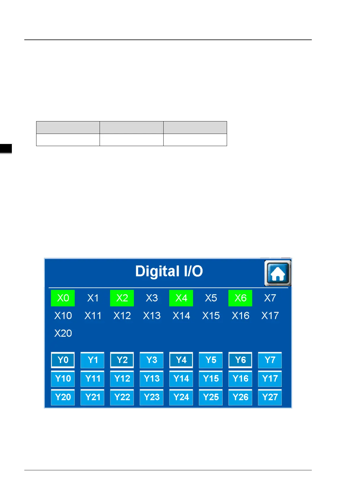
3.1.5 Digital I/O
Press Digital I/O from the main setting menu to display its corresponding setting page.
TP70P-211LC1T is with 17 digital inputs and 24 digital outputs. When an input point detects a signal, its corresponding
input point in the bulletin is highlighted in a green block. The output points Y0-Y27 can be pressed to send signal to its
corresponding devices. The example image shown above uses Y0, Y2, Y4, and Y6 to send signals and once X0, X2, X4
and X6 detect signals, the corresponding input points in the bulletin are highlighted in green blocks.
 Loading...