TP70P-211LC1T/TP04P-20EXL1T Operation Manual
5-4
5.2 Special Data Registers
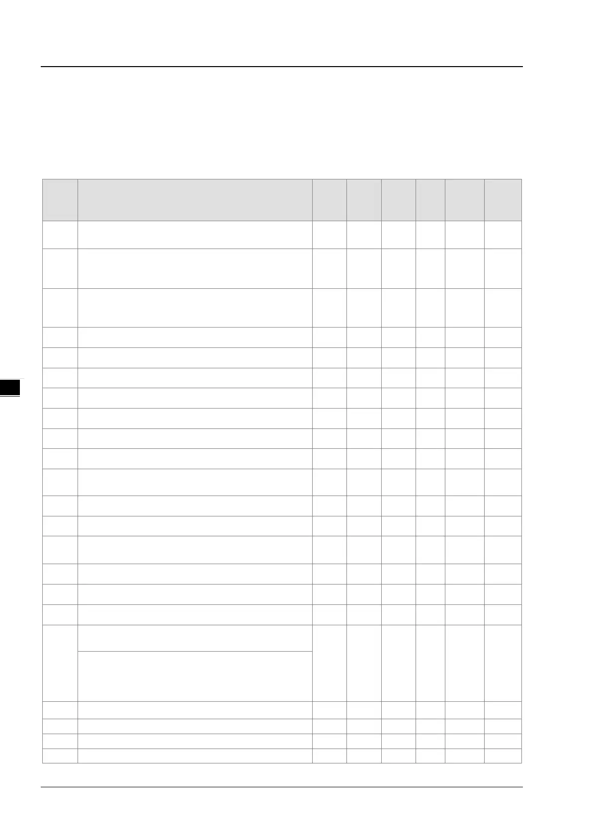
The types and functions of special data registers (special D) are listed in the table below. Some registers of
the same No. may bear different meanings for different PLC series. “R” in the column of Attribute refers to
“read only” and “R/W” refers to “read and write”; “-“ refers to the status remains unchanged and “#” refers to
the setting is based on the PLC setting status.
D
Content
OFF
ON
STOP
RUN
RUN
STOP
Attrib.
Latched
Default
D1000
Watchdog timer for program scan timeout (WDT)
(unit: ms)
300 - - R/W NO 300
D1001
TP firmware version
(for example when the value is HXX10, it indicates the
FW version is V1.0)
- - - R NO #
D1002
Program capacity
TP70P: 4K Steps
TP04P: 8K Steps
# - - R NO 4K / 8K
D1003 Sum of the PLC internal program memory - - - R YES -7920
D1004 Error code for syntax check 0 0 - R NO 0
D1008 Step address when WDT is ON 0 - - R NO 0
D1009 Low voltage signal (LV) occurance - - - R YES 0
D1010 Current scan time (Unit: 0.1 ms) # # # R NO 0
D1011 Minimum scan time (Unit: 0.1 ms) # # # R NO 0
D1012 Maximum scan time (Unit: 0.1 ms) # # # R NO 0
D1015
Value of accumulative high-speed timer (0~32,767, unit:
0 - - R/W NO 0
D1018 πPI (Low word) H’0FDB
H’0FDB
H’0FDB
R/W NO H’0FDB
D1019 πPI (High word) H’4049
H’4049 H’4049 R/W NO H’4049
D1022
Counting mode selection for AB phase counter
Only double and quad frequency are supported.
4 - - R/W NO 4
D1025 Code for communication request error 0 - - R NO 0
D1028 Index register E0 0 - - R/W NO 0
D1029 Index register F0 0 - - R/W NO 0
D1038
Response time delay setting when PLC is SLAVE in
COM2 (RS-485). Range: 0 ~ 10,000 (unit: 0.1 ms).
- - - R/W NO 0
By using PLC LINK in COM2 (RS-485), D1038 can be set
to send next communication data with delay. Range: 0 ~
10,000 (Unit: one scan cycle)
D1039 Fixed scan time (ms) 0 - - R/W NO 0
st
nd
rd
 Loading...