TP70P-211LC1T/TP04P-20EXL1T Operation Manual
4-6
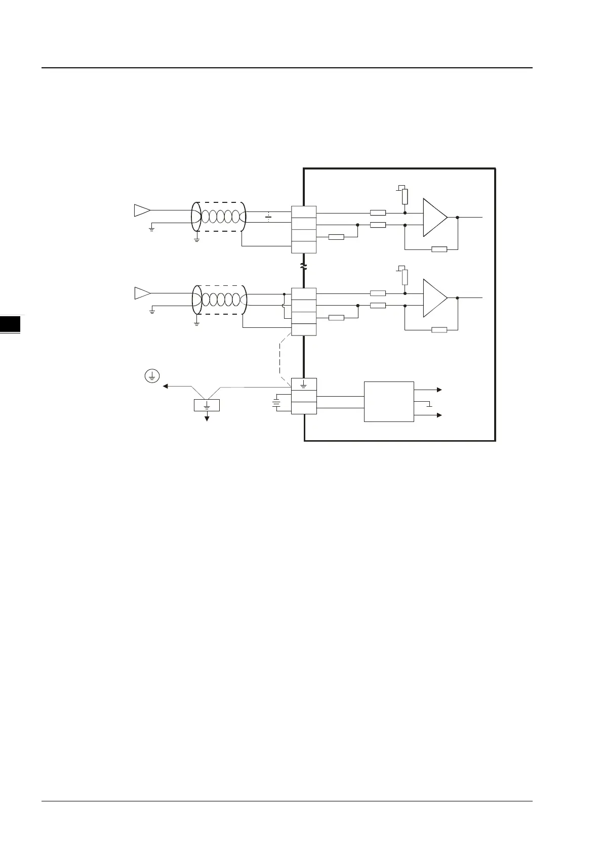
4.2.4 Wiring Analog Input Terminals
Only TP04P-20EXL1T has this feature analog voltage / current input in a range of V0+ ~ V3+.
TP70P-211LC1T does NOT include this feature.
-10V~+10V
V0+
V0-
CH0
-20mA~+20mA
V3+
I3
V3-
CH3
*3
*2
CH0
CH3
AG1
FE
FE
*4
Voltage input
Shielded
cable*1
Shielded
cable*1
Current input
I0
DC/DC
+15V
-15V
AG1
0V
+24V
DC24V
*5
converter
Ground
Impedance: b elow 100 Ω
CH0
AG1
AG1
Connected to
on a power supply m odule
System g round
*1. Use shielded cables to isolate the analog input signal cable from other power cables.
*2. If the module is connected to a current signal, the terminals V3+ and I3 must be short-circuited.
*3. If variability in the input voltage results in interference within the wiring, connect the module to a capacitor
with a capacitance between 0.1–0.47 μF and a working voltage of 25 V.
*4. To prevent too much noise and interference, connect the FE of the shielded cable to ground.
*5. Connect the ground terminal of a power supply module and the analog input terminal FE to the system ground and
then ground the system ground or connect the system ground to a distribution box
 Loading...