Chapter 4 Installation and Wiring
4-7
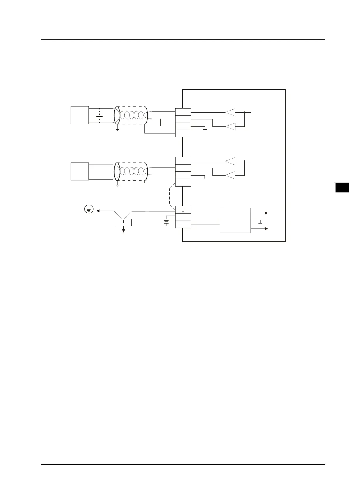
4.2.5 Wiring Analog Voltage / Current Output Terminals
Only TP04P-20EXL1T has this feature analog voltage / current input in a range of V4 ~ V5.
TP70P-211LC1T does NOT include this feature.
V5
I5
AG
CH5
0mA~20mA
CH5
AG1
V4
I4
AG
CH4
-10V~+10V
*2
CH4
AG1
FE
FE
*3
Voltage output
AC motor drive, recorder,
proportioning valve, e tc.
AC motor drive, recorder,
proportioning valve, e tc.
DC/D C
converter
+15V
-15V
AG1
0V
+24V
DC24V
*4
System ground
Shielded
cable*1
Shielded
cable*1
Current o utput
Connected to
on a power supply module
Ground
Impedance: b elow 1 00 Ω
*1. Use shielded cables to isolate the analog input signal cable from other power cables.
*2. If variability in the input voltage results in interference within the wiring, connect the module to a capacitor
with a capacitance between 0.1–0.47 μF and a working voltage of 25 V.
*3. To prevent too much noise and interference, connect the FE of the shielded cable to ground.
*4. Connect the ground terminal of a power supply module and the analog input terminal FE to the system ground and
then ground the system ground or connect the system ground to a distribution box
 Loading...