I/O support Digital I/O support
Digi XBee® 3 Zigbee® RF Module
168
Digital I/O support
Digital I/O is available on lines DIO0 through DIO12 (D0 (DIO0/AD0/Commissioning Button
Configuration) - D9 (DIO9/ON_SLEEP) and P0 (DIO10/RSSI Configuration) - P4 (DIO14/DIN
Configuration)). Digital sampling is enabled on these pins if configured as 3, 4, or 5 with the following
meanings:
n 3 is digital input.
l Use PR (Pull-up/Down Resistor Enable) to enable internal pull up/down resistors for each
digital input. Use PD (Pull Up/Down Direction) to determine the direction of the internal pull
up/down resistor.All disabled and digital input pins are pulled up by default.
n 4 is digital output low.
n 5 is digital output high.
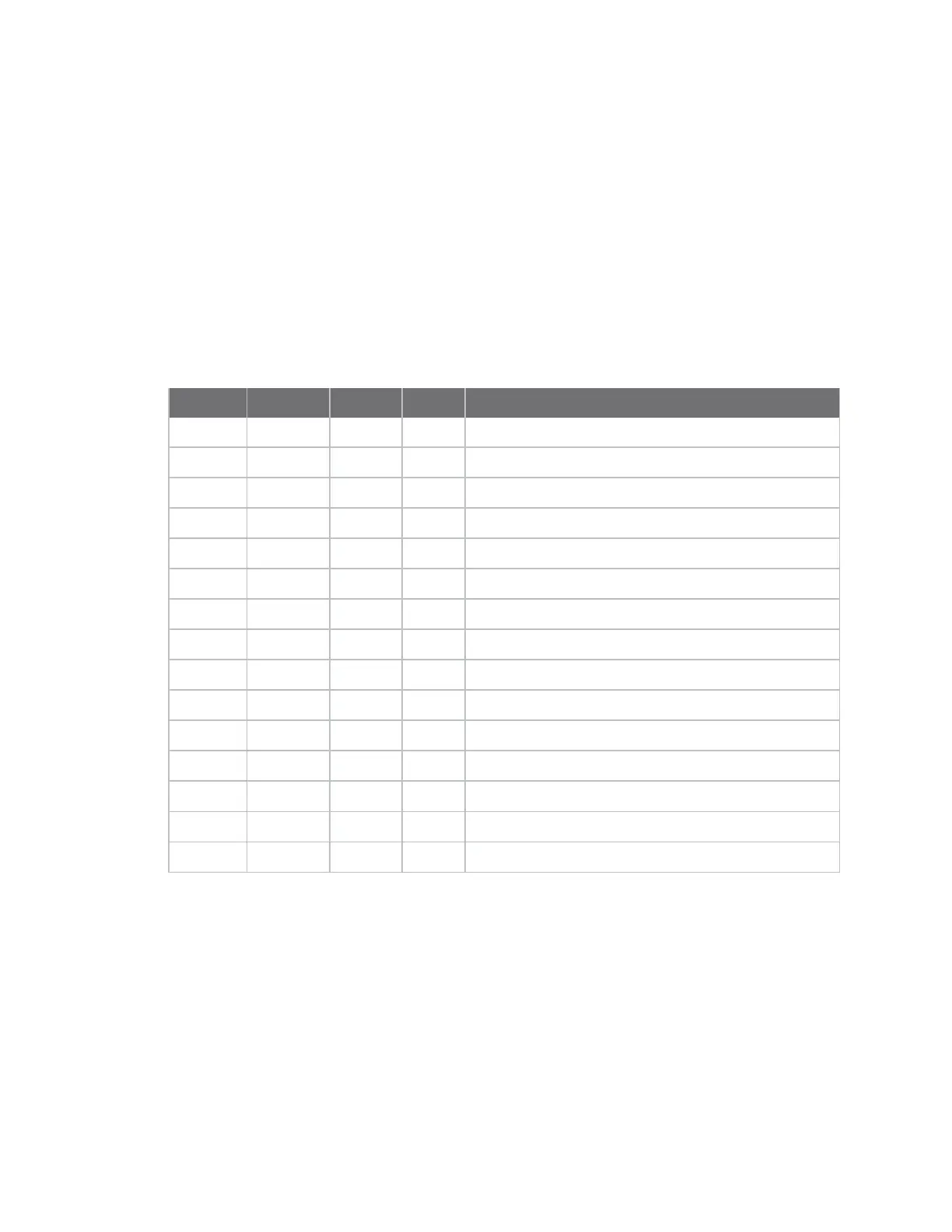
Function Micro Pin SMT Pin TH Pin AT Command
DIO0 31 33 20 D0 (DIO0/AD0/Commissioning Button Configuration)
DIO1 30 32 19 D1 (AD1/DIO1/TH_SPI_ATTN Configuration)
DIO2 29 31 18 D2 (DIO2/AD2/TH_SPI_CLK Configuration)
DIO3 28 30 17 D3 (DIO3/AD3/TH_SPI_SSEL Configuration)
DIO4 23 24 11 D4 (DIO4/TH_SPI_MOSI Configuration)
DIO5 26 28 15 D5 (DIO5/Associate Configuration)
DIO6 27 29 16 D6 (DIO6/RTS)
DIO7 24 25 12 D7 (DIO7/CTS)
DIO8 9 10 9 D8 (DIO8/DTR/SLP_RQ)
DIO9 25 26 13 D9 (DIO9/ON_SLEEP)
DIO10 7 7 6 P0 (DIO10/RSSI Configuration)
DIO11 8 8 7 P1 (DIO11 Configuration)
DIO12 5 5 4 P2 (DIO12/TH_SPI_MISO Configuration)
DIO13 3 3 2 P3 (DIO13/DOUT Configuration)
DIO14 4 4 3 P4 (DIO14/DIN Configuration)
I\O sampling is not available for pinsP5throughP9. See the XBee 3 Hardware Reference Manual for full
pinouts and functionality.
Analog I/O support
Analog input is available onD0throughD3. Configure these pins to 2 (ADC) to enable analog sampling.
PWM output is available onP0andP1,which can be used for Analog line passing.Use M0 (PWM0 Duty
Cycle)andM1 (PWM1 Duty Cycle) to set a fixed PWM level.

 Loading...


