17
IP2371EN
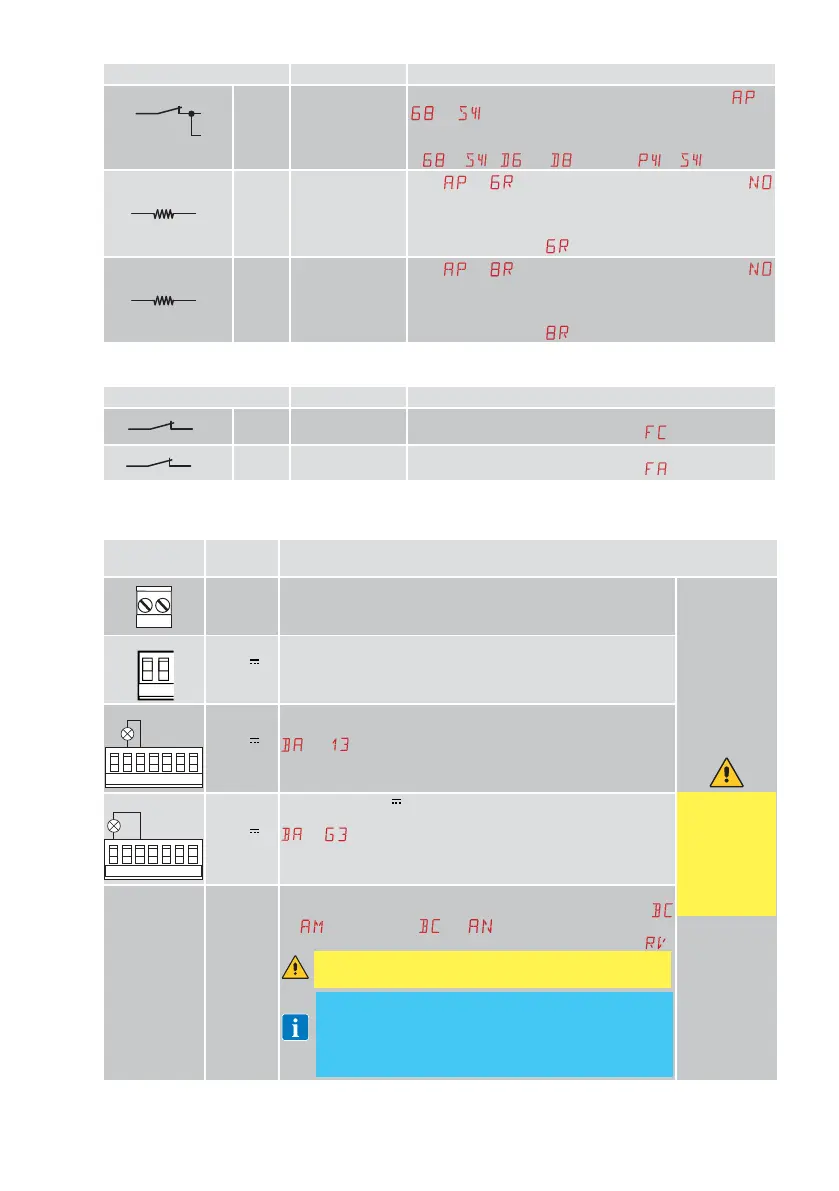
Command Function Description
1
6
8
NC
CLOSING/OPEN-
ING SAFETY
DEVICE
For safety devices with self-test input: When selecting
→
→ , connect the output contact of the safety device
to terminals 1-6-8 on the control panel (in series with the
photocell output contact, if installed).
If
→ , and cannot be or .
1
6R R= 8.2kΩ
OPENING
RESISTIVE
SAFETY EDGE
With
→ selected, confirmed by the message
on the display, a short circuit or open circuit state of the
resistance triggers arrest with disengagement and reverses
the direction of the automation in accordance with the value
set for the parameter
.
1 8R R= 8.2kΩ
CLOSING
RESISTIVE
SAFETY EDGE
With
→ selected, confirmed by the message
on the display, a short circuit or open circuit state of the
resistance triggers arrest with disengagement and reverses
the direction of the automation in accordance with the value
set for the parameter
.
4.3 Limit switch inputs
Command Function Description
0
11A
NC
CLOSING LIMIT
SWITCH
Extra low voltage limit switch logic contact. Its behaviour
depends on the value set in parameter
.
0 12 A
NC
OPENING LIMIT
SWITCH
Extra low voltage limit switch logic contact. Its behaviour
depends on the value set in parameter
.
5. Outputs and accessories
Output
Value of
accessories
Description
24V~
24 V~
0.3 A max
AC power supply to accessories
Output for power supply to external accessories.
The total sum
of the current
values deliv-
ered by 30,1
and
24 V~
outputs must
never exceed
0.5 A.
0
-
1
+
24 V
0.3 A max
Accessories power supply
Output for DC power supply to external accessories.
3W max
30 2 3 4 9
13G3
24 V
0.3 A max
Automation status lamp (configurable)
For the operating mode of output 30-13, refer to the selection
→ .
3W max
30 2 3 4 9
13G3
24 V
0.3 A max
Configurable 24 V
output
For the operating mode of output 30-G3, refer to the selection
→ .
AUX 1
AUX 2
GOPAVRS
LAB9
BIXR2
BIXPR2
MOBCRE
LAN7S
The control panel has two slots for plug-in command and safety
boards. The action of the control board can be selected using
→
for AUX1 and → for AUX2. When using slot-in
radio boards, remove the RDX module. The display will show
.
WARNING: the plug-in cards must be inserted and removed
with the power supply disconnected.
NOTE: the current absorption of the accessories installed in the
slots AUX1/AUX2 if associated with output “1” by the relative jumper,
must be considered in the total current deliverable by output 1 (0.3 A).
Differently if associated to “30” must be considered in the calculation
of the total current deliverable by output 30 (0.3 A).
 Loading...


