18
IP2371EN
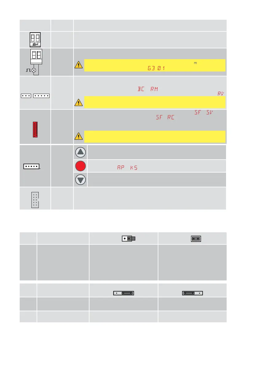
Output
Value of
accessories
Description
ANTENNA
Input for GOL148REA external antenna or rigid wire antenna supplied according to
the operating frequency of the receiver module used.
~
LP
230 V~
25 W max
230 V flashing light
For connection of a 230 V~ flashing light with auto-flashing function.
WARNING: if you want to use the FL24 flashing light (24V ), connect it to
output 30-G3 and set parameter
= .
RDX
ZENRS
ZENPRS
(optional)
For installation of a ZENRS (433.92 MHz) or ZENPRS (868.35 MHz) type radio
receiver module.
Operation is enabled by selecting
→ .
When using slot-in radio boards, remove the RDX module. The display will show
.
WARNING: the modules must be inserted and removed with the power
supply disconnected
COM
BIXMR2
COM - Enables saving of operating configurations with function → . Saved
configurations can be recalled with function
→ . The storage module allows
the remote controls to be stored. If the control panel is replaced, the storage
module being used can be inserted in the new control panel.
WARNING: the storage module must be inserted and removed with the
power supply disconnected, and paying attention to the positioning direction.
J29
PT3
(optional
for LCA85
- included
in LCA85B)
Membrane push-button panel (PT3). Starts the opening operation.
NOTE: to activate the closing operation, connect the connector of the
push-button panel to J29 (rotated by 180°).
Membrane push-button panel (PT3). Causes the blocking of the movement.
See parameter
→
Membrane push-button panel (PT3). Starts the closing operation.
NOTE: to activate the opening operation, connect the connector of the
push-button panel to J12 (rotated by 180°).
SCI
FUTURE
USE
6. Jumper setting
Jumper Description
OFF
ON
JR1 Display mode selection Display mode
The values and parameters present
can be only displayed.
Maintenance mode
Maintenance mode. The values
and parameters present can be
displayed and modified. Activated
maintenance mode is indicated by
the permanent lit on of the right-
hand point on the display.
Jumper Description
30 1
30 1
AUX1 Selection of power supply
- auxiliary board 1
AUX1 powered from 0-1 AUX1 powered from 0-30 (default
setting)
AUX2 Selection of power supply
- auxiliary board 2
AUX2 powered from 0-1 AUX2 powered from 0-30 (default
setting)
 Loading...


