Dräger Medical AG & Co. KGaA 6173.3
All rights reserved. Copyright reserved.
_ _Printed on_18.05.05_F61733XXT01.fm
31
Function description Babylog 8000
8 Description of Pneumatic Functions
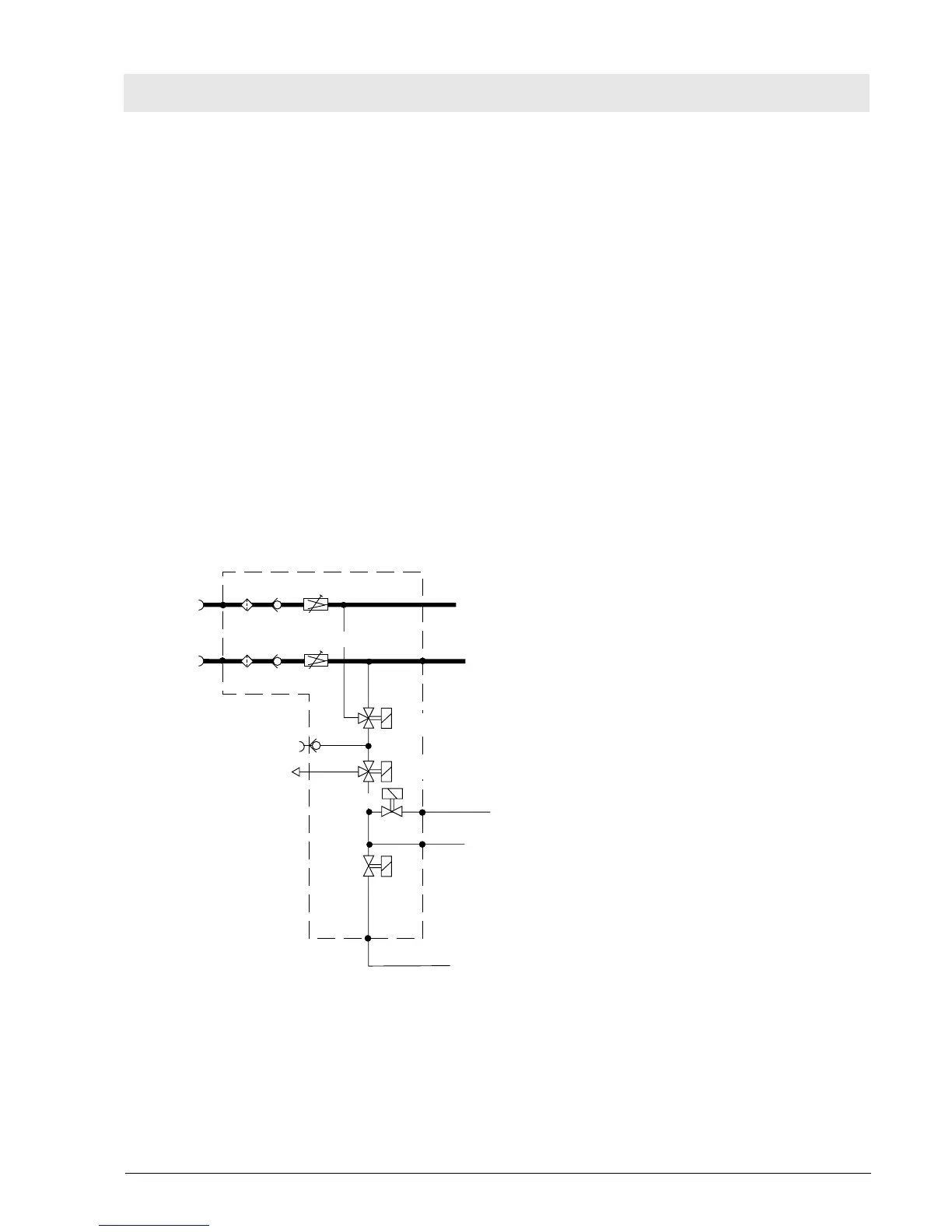
8.1 Gas Supplies
AIR and O
2
flow through the filters F 1.1 and F 1.2 and the check valves D 1.1 and D1.2 to the pressure
regulators DR 1.1 and DR 1.2 which regulate the gases to a constant system pressure.
From the pressure regulators DR 1.1 and DR 1.2 the gases flow to the mixing and flow-control unit. The
gas mixture created there flows through the inspiratory line to the patient.
AIR and O
2
are taken downstream of the pressure regulators DR 1.1 and DR 1.2 and delivered to the
solenoid Y 1.1. If one of the gases fails, this solenoid switches over to the other one.
If the power supply is interrupted or if a stenosis 2 situation has occurred, solenoid Y 1.2 switches over to
emergency venting.
The gas for O
2
calibration flows through solenoid Y 1.3.
The gas required to control the ejector flows through solenoid Y 1.4.
Fig. 8: Compressed-gas connection
AIR
O
2
F1.2
F1.1
DR1.2
DR1.1
D1.2
D1.1
Y1.1
Y1.2
Y1.3
Y1.4
Y1.5
6
5
4
3
1
2
To mixing and flow-control unit
To mixing and flow-control unit
 Loading...