Dräger Medical AG & Co. KGaA 6173.3
All rights reserved. Copyright reserved.
_ _Printed on_18.05.05_F61733XXT01.fm
47
Function description Babylog 8000
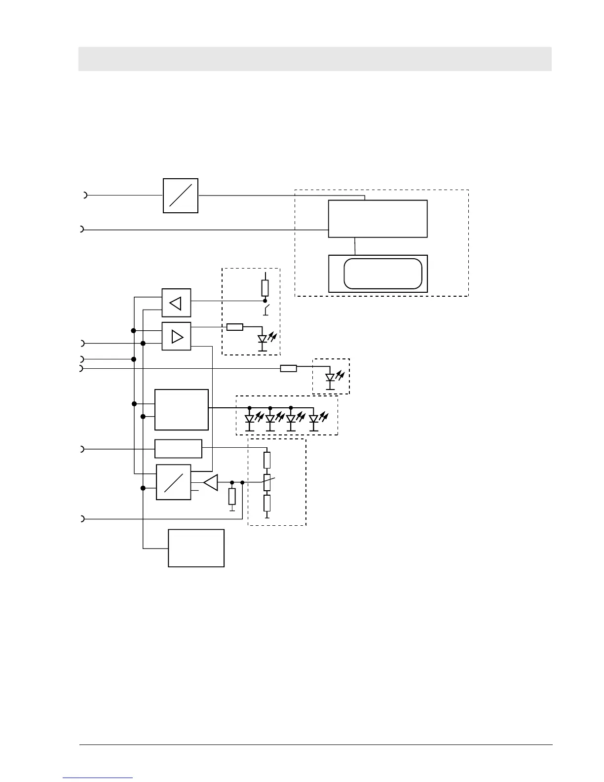
10.9 Front PCB (Babylog 8000/Babylog 8000 plus with EL Display)
The Front PCB reads in the keys of the potentiometer and display field, controls the LEDs of the
potentiometer and display field, powers the EL display with operating voltage (contrast), and generates
the control signal for the bargraph.
Fig. 23: Block diagram of the Front PCB
DC
DC
+5 V, +12 V
EL display, complete
EL display converter
EL display
Cable of EL display
key port
Keys and option switches of the front panel
LEDs of the front panel
Alarm LEDs
Bargraph of the monitoring field
Potentiometer of the potentiometer field
LED driver
Amplifier
Bargraph
URef
A
D
6x
Adress
decoder
UB
Control bus
und
Adress bus
Data bus
Test A/D-Wandler
 Loading...