Dräger Medical AG & Co. KGaA 6173.3
All rights reserved. Copyright reserved.
_ _Printed on_18.05.05_F61733XXT01.fm
41
Function description Babylog 8000
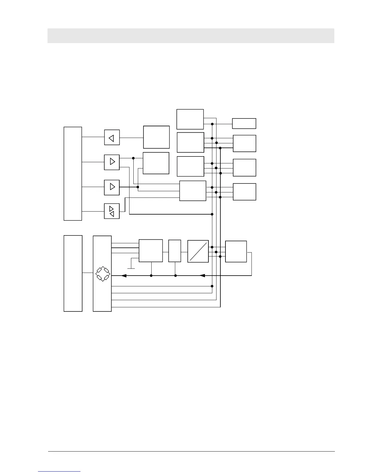
10.5 Flow PCB (Babylog 8000/Babylog 8000 plus) (optional)
The Flow PCB in Babylog 8000/Babylog 8000 plus measures the flow. It provides the following function
blocks: sensor bridges with sensor amplifiers, analog-to-digital converter, microprocessor Z80 minimum
system, Z80-68000 bus interface.
Fig. 18: Block diagram of the Flow PCB
Digital bus 68000
DTACK
Control bus
Adress bus
Data bus
DTACK
generator
Adress
decoder
Adress
decoder
EPROM
64 k / 32 k
RAM
8 k / 2 k
Dual-Port-
RAM
6 MHz
Z80
CPU
Timer
Watchdog
Control bus
Adress bus
Data bus
System reset
Flow sensor
Muxer
S
&
H
A
D
PIO
Analog 1
Analog 4
Status flow
Control bus
Adress bus
Data bus
 Loading...