Electrical Installation
16
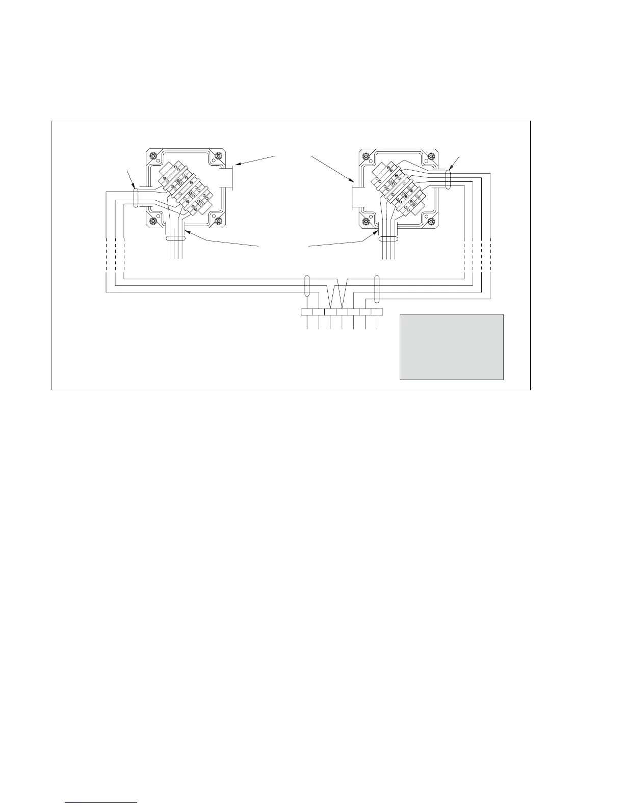
Figure 6: Connection diagram powered individually
Receiver
terminal box connections
Transmitter
terminal box connections
Blanking
Plug
supplied
Blanking
Plug
supplied
NOTES:
1) Glands to be EEx e type e.g. Hawke 501/453/UNIV/...
2) Entry points may be changed provided that the correct connections
are maintained.
3) The Transmitter and Receiver assemblies must be securely earthed.
4) These connections are typically made in the marshalling cabinet in the
non-hazardous area.
5) It is essential for correct operation that the Digital and Common lines
of the Tx and Rx are interconnected even when they are not connected
to external equipment.
1
1
2
2
3
3
4
4
5
5
6
6
7
7
S
S
E
E
1
1
2
2
3
3
4
4
5
5
6
6
7
7
S
S
E
E
To
Receiver
head unit
EEx e gland
supplied fitted
To
Transmitter
head unit
CAUTION
This diagram must be followed
to ensure correct operation,
whether the installation is in a
hazardous area or not.
For safe operation in a hazardous
area you must also refer to
the certification documents and
comply with all local regulations.
+24V dc
+24V dc
Common
Digital
cable screen
cable screen
0-20mA
(See notes 4 and 5)
Instrument
Earth
Instrument Earth
See note 2
00623892.eps

 Loading...