Cabling the EEx d Certified Connector
20
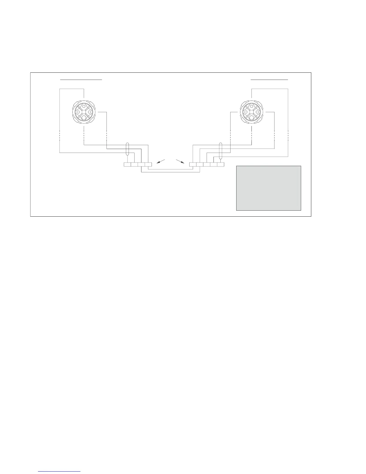
Figure 10: Connection diagram powered individually using CEAG EEx d connector
01223892.eps
NOTES:
1) The Transmitter and Receiver assemblies must be securely earthed.
2) These connections are typically made in the marshalling cabinet in the non-hazardous area.
3) It is essential for correct operation that the Digital and Common lines of the Tx and Rx
are int
erconnected even when they are not
connected to external equipment.
CAUTION
This diagram must be followed
to ensure correct operation,
whether the installation is in a
hazardous area or not.
For safe operation in a hazardous
area you must also refer to
the certification documents and
comply with all local regulations.
+24V
dc
+24V
dc
Common
Digital
Digital
Common
0-20mA
(See notes 2 and 3)
Instrument
Earth
Instrument Earth
33
22
11
44
Rear of eXLink
socket
Rear of eXLink
socket
Receiver ConnectionsTransmitter Connections

 Loading...