Understanding The System
6
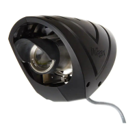
Transmitter
The Transmitter is a three-wire device, with cable terminals for (i) 24Vdc power; (ii) digital communication; and (iii) power and signal com-
mon. The connector for the Handheld Terminal allows data coming from the Receiver to be viewed at the Transmitter, including the graph-
ical display of orientation and signal strength needed for alignment. The Handheld can also configure the Transmitter with its operating
channel and a user-entered tag reference. The eye-safe optical output through the (electrically heated) Transmitter lens is mainly infrared,
although a controlled amount of deep red light is visible. An Attenuator Plate is fitted over the lens for operating distances below 16m. A
central section in the plate is removed for distances between 8 and 16m, retained for distances between 4 and 8m.
There are five operating modes:
1 Normal Mode. Flashes of normal intensity are output once a second. The flash rate appears regular to the eye, although it is phase-
coded to send directional information to the Receiver. Occasionally a flash will be seen out of the normal sequence as part of an inter-
nal self-test cycle.
2 Strong Mode. Flashes of increased intensity are output at a regular 4Hz rate.
3 Alignment Mode. Flashes of normal intensity are output four times a second. It is easily distinguishable from Strong Mode because
there is a noticeable irregularity to the flash rate as it sends directional information to the Receiver.
4 Low-supply Mode. Flashes of increased intensity are output at a regular 2Hz rate. This is substituted for Alignment Mode if the Trans-
mitter detects that the supply voltage dips below the specified range when tested with the lens heater on. This test is only carried out
during alignment (and hence at the time of commissioning the detector) so that it cannot delay a gas alarm if this coincides with a dete-
riorating supply.
5 Fault Mode. Flashes of maximum intensity are output at a regular 1Hz rate. This is substituted for Normal Mode if the Transmitter has
detected that a tube has failed or is intermittent. It is also the way the Transmitter signals to the Receiver that the link between them
has been broken. Visually it is not distinguishable from Normal Mode, but is detected by the Receiver to provide warning signals.
Receiver
The Receiver is a four-wire device, with cable terminals for (i) 24Vdc power; (ii) analogue current loop; (iii) digital communication; and (iv)
power and signal common. The analogue output provides fully linearised 4-20 mA gas readings and configurable warning signals. It can
be used in both current-source and current-sink circuits. The digital line supplies the signals to switch the Transmitter mode and can
optionally be routed to the Non-hazardous Area to provide two-way digital communications with the AI500 interface. Like the Transmitter,
the Receiver has both an electrically heated lens and a port for the Handheld Terminal, providing a clear display of present readings and
the ability to alter the Polytron Pulsar 2s configuration, operating channel, and tag reference. For more detail about the facilities offered
by the AI500 and the Handheld Terminal please see 'Digital Communications' below and the Appendices.
The data logger in the Receiver maintains a non-volatile record for the previous seven days of operation, with consolidated records for the
previous 32 weeks. These logs include such essential information as supply voltage, internal temperature, signal strength and Transmitter
and Receiver alignment. Draeger PLMS software is available which interprets and displays the logged data on a PC running under MS
Windows. When used in conjunction with the AI500 interface the software allows a permanent archive of the detailed version to be kept
on disk. The disk record will be continuous provided the Receiver log is interrogated at least once per week.
 Loading...