Cabling the EEx d Certified Connector
18
Preparing and fitting the cable
● Strip and prepare the cable to the required lengths, typical dimensions are given in Figure 9.
● Place the socket components (outer cap, thrust washers, outer seal etc.) onto the cable (see Figure 7), whilst ensuring that the cable
armour/braid is fitted between the clamp cone and sleeve.
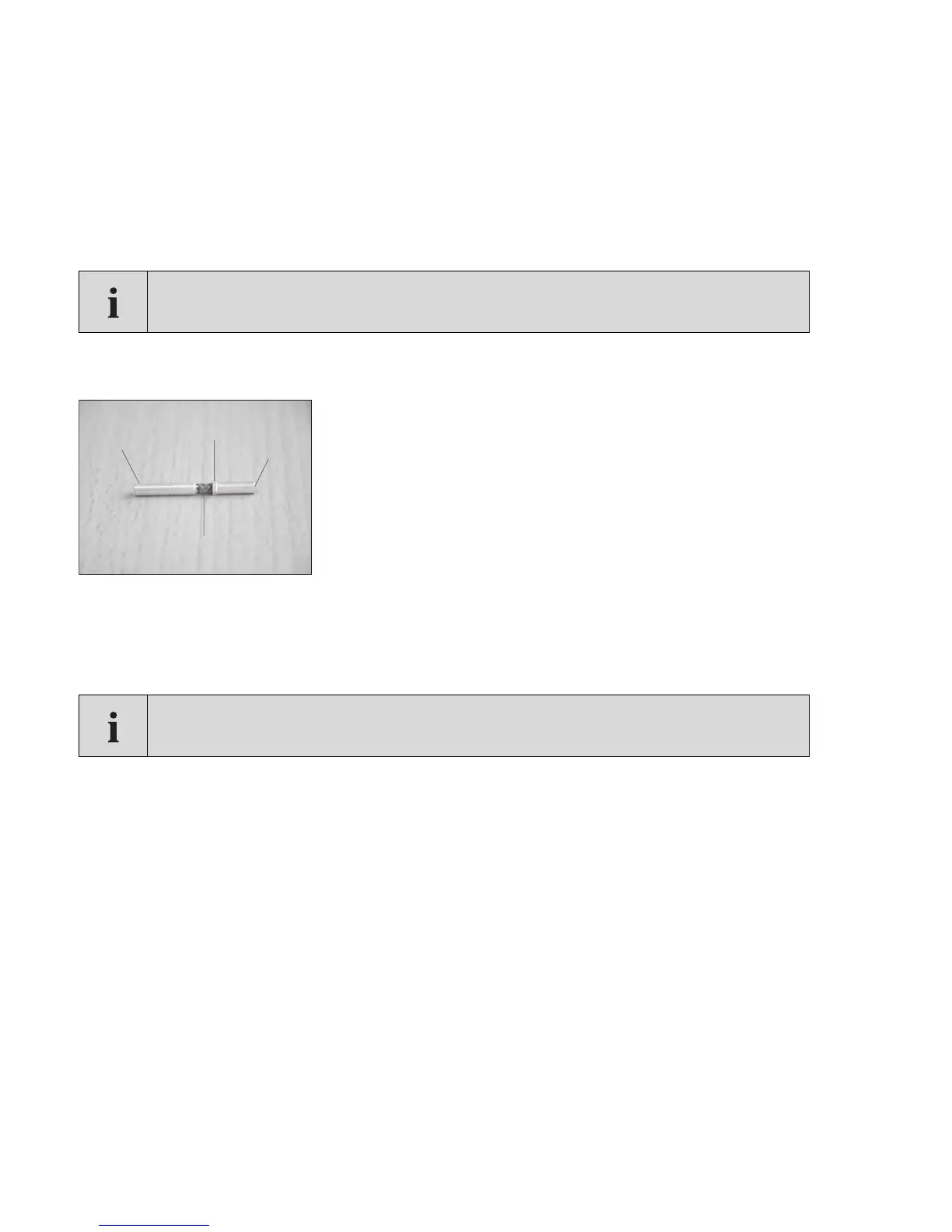
● Fit the contact pins to the cable ends, (ensuring that small hexagonal collar sits between the cable core and colour coded bar, see
Figure 8
● Carefully crimp the pins into position, ensuring that the hexagonal collar is not damaged during the process. A crimping tool is recom-
mended and is available from Draeger Safety UK Ltd or your local distributor
Figure 8
1 Contact end (connects with plug)
2 Hexagonal collar
3 Crimp end (fit to cable)
4 Colour coded bar
● Push the insulation sleeve over the contact pins, and push fit each pin into its appropriate location of the socket insert. See rear socket
insert as indicated in Figure 9 for termination descriptions (e.g. pin 1 = digital, pin 2 = 24V, pin 3 = 0-20mA, pin 4 = Common).
NOTE
that the -ve core (common) MUST have the large contact pin fitted, the pins are colour coded so that the
large pin is easily distinguishable from the other 3 pins.
IMPORTANT
It is critical that each pin is fitted to the correct location; failure to do so may result in damage to the Dräger
Polytron Pulsar 2.
00923892.eps
4
3
2
1

 Loading...