The Dräger Polytron Pulsar 2 Digital Interface AI500
40
Connector 3: Hand-held Terminal Port
Removable polarised connector
Phoenix Contact MC 1.5/06-ST-3.81, 1.5mm
2
(16AWG)
The adaptor cable Draeger-PLMS 2350326 allows connection of the Handheld Terminal (or Communicator). The port complies with the
requirements of its Intrinsic Safety certification.
Communicating with the AI500 Digital Interface
For most purposes the AI500 can be used with equipment and software supplied by Draeger-PLMS, relieving the user of the need to
know the details of its digital communications. Information can be provided for writers of software for a remote processor, acting as Mas-
ter of a multidrop system, to address one or more AI500 units as Slaves. For this purpose the AI500 acts as a dual-port memory which is
automatically filled with the most up-to-date values for a wide range of measured parameters from the connected
Dräger Polytron Pulsar 2s (gas reading, signal and noise levels, x y alignments of Transmitter and Receiver, supply voltage, temperature
etc), their internal configurations (gas calibration, serial number, tag designation etc), and their internal data logger records. The data is
available for immediate access at data rates of 1200 or 9600 baud.
Summary of Draeger-PLMS Protocol
All data is binary in frames of fixed length. Bytes are 8-bit, non-parity, sent least significant bit first with one stop bit. A Short Format frame
of five bytes is used for simple commands and acknowledgements. A Long Format frame of 24 bytes or an Extra-long Format frame of
263 bytes is used to transfer data and configurations. Configurations are 16 byte blocks, including an internal CRC 16 checksum in addi-
tion to the CRC 16 checksum used to transmit them. If synchronisation between Master and Slave is lost then any garbled or incomplete
frame is discarded after a checksum error, a stop bit error, or the absence of an expected start-bit after two byte durations.
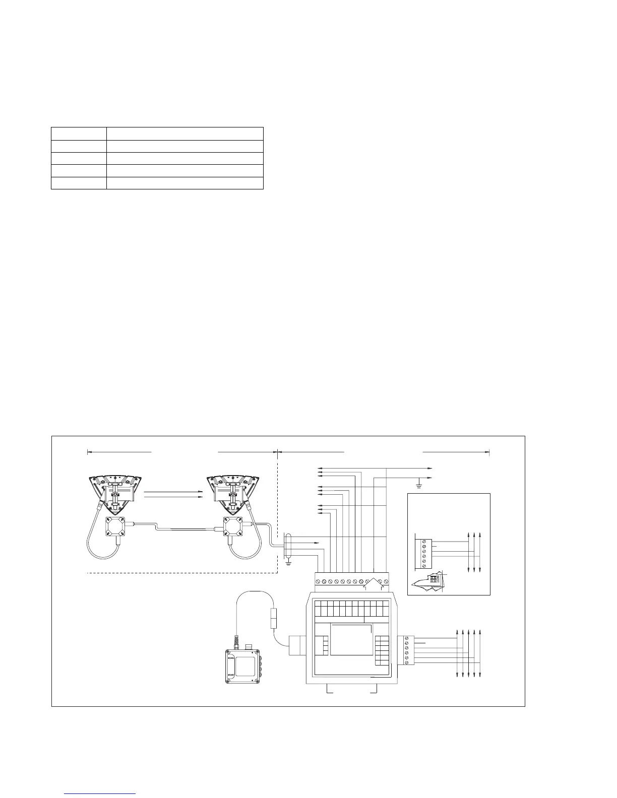
Figure 13: Connection from the field device to the AI500
Terminal:
Optical Isolator Function:
19 Emitter (volt-free output -)
20 Collector (volt-free output +)
21 Anode (volt-free input +)
22 Cathode (volt-free input -)
14
15
16
17
20
21
22
19
18
119876543210112
13
+5V out
TXB/RXB'(+)
RXB' (+)
TXB (+)
TXA/RXA' (-)
RXA' (-)
TXA (-)
TXB (+)
RXB' (+)
TXA (-)
RX A'(-)
0V (ref)
0V (ref)
0V (ref)
RS-422 / 485
PORT
18-32V dc
HANDHELD
DIGITAL
INTERFACE
TYPE AI500
This device complies with part 15 of the FCC Rules.
Operation is subject to the following two conditions:
1) This device may not cause harmful interference, and
2) This device must accept any interference received,
including interference that may cause undesired operation.
++
PULSAR DIGITAL I/O
BCDA
COMMON
COMMON
COMMON
COMMON
COMMON
COMMON
+24V dc
+24V dc
0-20mA
Digital
Common
Common
Detector A
Detector B
Detector C
Detector D
RS-485
Master
(see note 5)
RS-422/485 Master
(see note 5)
RS-422/485
connection to
4-wire system
RS-485
connection to
2-wire system
Handheld Terminal
with Adaptor Cable
NOTES:
HAZARDOUS AREA NON-HAZARDOUS AREA
1) One to four Pulsar detectors may be connected to each
Digital Interface.
2) Up to 32 Digital Interfaces may be interconnected.
3) For alternative Pulsar wiring options refer
to manual.
4) Loading of +5V dc output must not exceed 100mA.
5) RS422/485 Port (Terminals 13 to 18)
Markings A, B, A', B' as ISO/IEC 8482:1993.
Markings (+) and (-) show polarity for binary 1, stop-bit and
idle-states. The host (master) system must provide
idle-state biasing with this polarity.
6) Remove front cover for access to links.
7) Interface clips onto standard 15, 32 and 35mm
mounting rails.
(see note 2)
(see note 4)
(see note 4)
(see note 2)
(see note 6)
(see note 7)
(see note 1)
RS422/485 - 2W | 4W
(Instrument Earth)
Instrument
Earth
Receiver
Transmitter
Link cable (4-wire)
Detector A
(see note 3)
IR
OUT
01923892.e
 Loading...