Introduction
1-5
About DAE2P and DAE3P disk enclosures
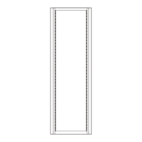
Figure 1-3 DAE2P/DAE3P rear components
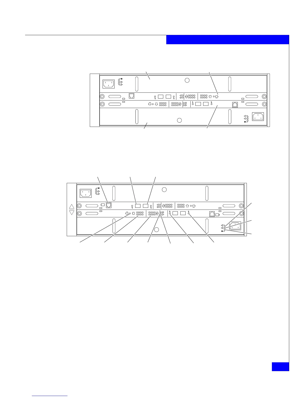
Figure 1-4 Disk enclosure rear view — LEDs and connectors
As shown in Figure 1-5, an enclosure address (EA) indicator is
located on each LCC. (The EA is sometimes referred to as an
enclosure ID.) Each link control card (LCC) includes a bus (loop)
identification indicator. The storage processor initializes bus ID when
the operating system loads.
!!
!!
!
EXP PRI
EXPPRI
#
!
EXP PRI
EXPPRI
#
Power/Cooling Module B Link Control Card B
Power/Cooling Module A Link Control Card A
EMC3232
!!
!!
!
EXP PRI
EXPPRI
#
!
EXP PRI
EXPPRI
#
A
B
+
-
+
-
Primary
Link
Active
Expansion
Link
Active
Expansion
(Out)
Primary
(In)
SPS (Not used in
CLARiiON)
Fault
(Amber)
Power
(Green)
Loop
(Bus) ID
Enclosure
Address
EA Selection
Blower
Fault
(Amber)
Power
Fault
(Amber)
Power
EMC3209
 Loading...