3-14
DAE2P/DAE3P Hardware Reference
Servicing a DAE2P/DAE3P
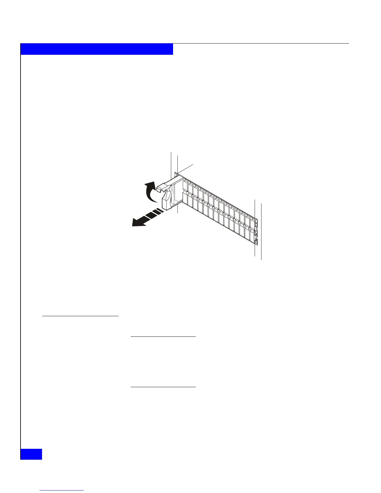
2. If the active light is on steadily, pull the latch, and slowly pull the
module about 1 in (3 cm) from its slot. Wait 30 seconds for the
disk to stop spinning. Then remove the module and place it on a
padded, static-free surface.
If the active light is off or mostly off you do not need to wait for
the disk to stop spinning. Pull the latch and slowly pull the
module from its slot, as shown in Figure 3-8. Place it on a padded,
static-free surface.
Figure 3-8 Removing a disk module
Continue to the next section to install the replacement disk module.
Installing a disk or filler module
Always replace a disk drive with another of the same type/model; do not
mix Fibre Channel and SATA components in an enclosure. Refer to Figure 3-5
on page 3-10 for a visual comparison of disk carriers.
An enclosure running at 4 Gb/s will recognize only 4 Gb disks (with a 2/4
mark on the front label). A DAE2P will support 4 Gb disks at 2 Gb/s.
1. Make sure an ESD wristband is attached to your wrist and the
enclosure (see the precautions on page 3-7).
2. Align the module with the guides in the slot.
EMC2174
 Loading...