3-6
DAE2P/DAE3P Hardware Reference
Servicing a DAE2P/DAE3P
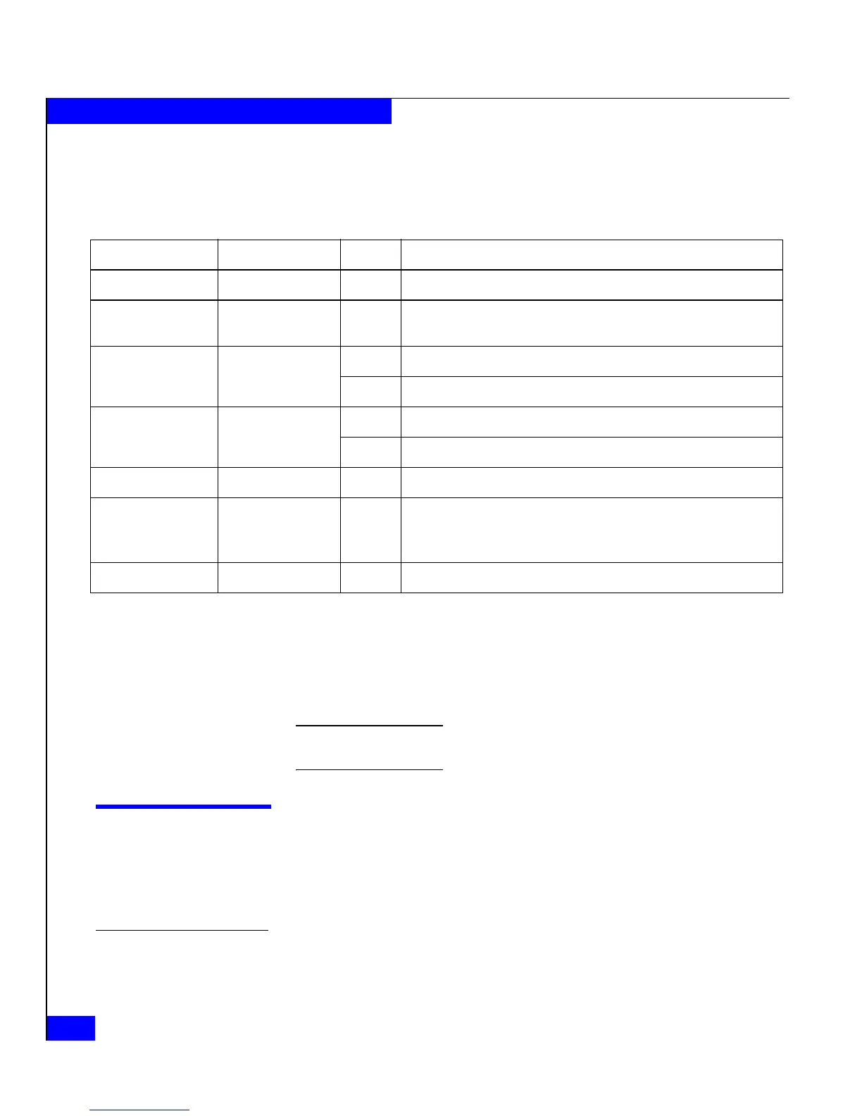
Table 3-3 describes the status LEDs visible from the rear of the disk
enclosure.
If the disk enclosure Fault light is on, examine the other status lights
to determine which FRU(s) is faulty. If a fault light on a FRU remains
on, you should replace that FRU as soon as possible.
When a redundant FRU fails, high availability will be compromised until you
replace the faulty FRU.
Handling FRUs
This section describes the precautions that you must take and the
general procedures you must follow when removing, installing, and
storing FRUs.
Power issues and
FRUs
The DAE2P/DAE3P is designed to always be powered up and hot
repairable. Its front bezel should be attached and each of its
Table 3-3 Status lights visible from the rear of the disk enclosure
Light Quantity Color Meaning
LCC Power 1 per LCC Green On when the LCC is powered up.
LCC Fault 1 per LCC Amber On when either the LCC or a Fibre Channel connection is faulty.
Also on during Power On Self Test (POST).
Primary Link Active 1 per LCC Green On when Primary connection is active; back-end bus running at 2Gb
Blue On when Primary connection is active; back-end bus running at 4Gb
Expansion Link Active 1 per LCC Green On when Expansion connection is active; back-end bus running at 2Gb
Blue On when Expansion connection is active; back-end bus running at 4Gb
Power Supply Active 1 per supply Green On when the power supply is operating.
Power Supply Fault* 1 per supply Amber On when the power supply is faulty or is not receiving AC line voltage.
Flashing when either a multiple blower or ambient overtemperature
condition has shut off dc power to the system.
Blower Fault* 1 per cooling module Amber On when a single blower in the power supply is faulty.
* The DAE2P/DAE3P will continue running with a single power supply and three of its four blowers. Removing a power/cooling module constitutes a
multiple blower fault condition, and will power down the enclosure unless you replace a blower within two minutes.
 Loading...