3-4
DAE2P/DAE3P Hardware Reference
Servicing a DAE2P/DAE3P
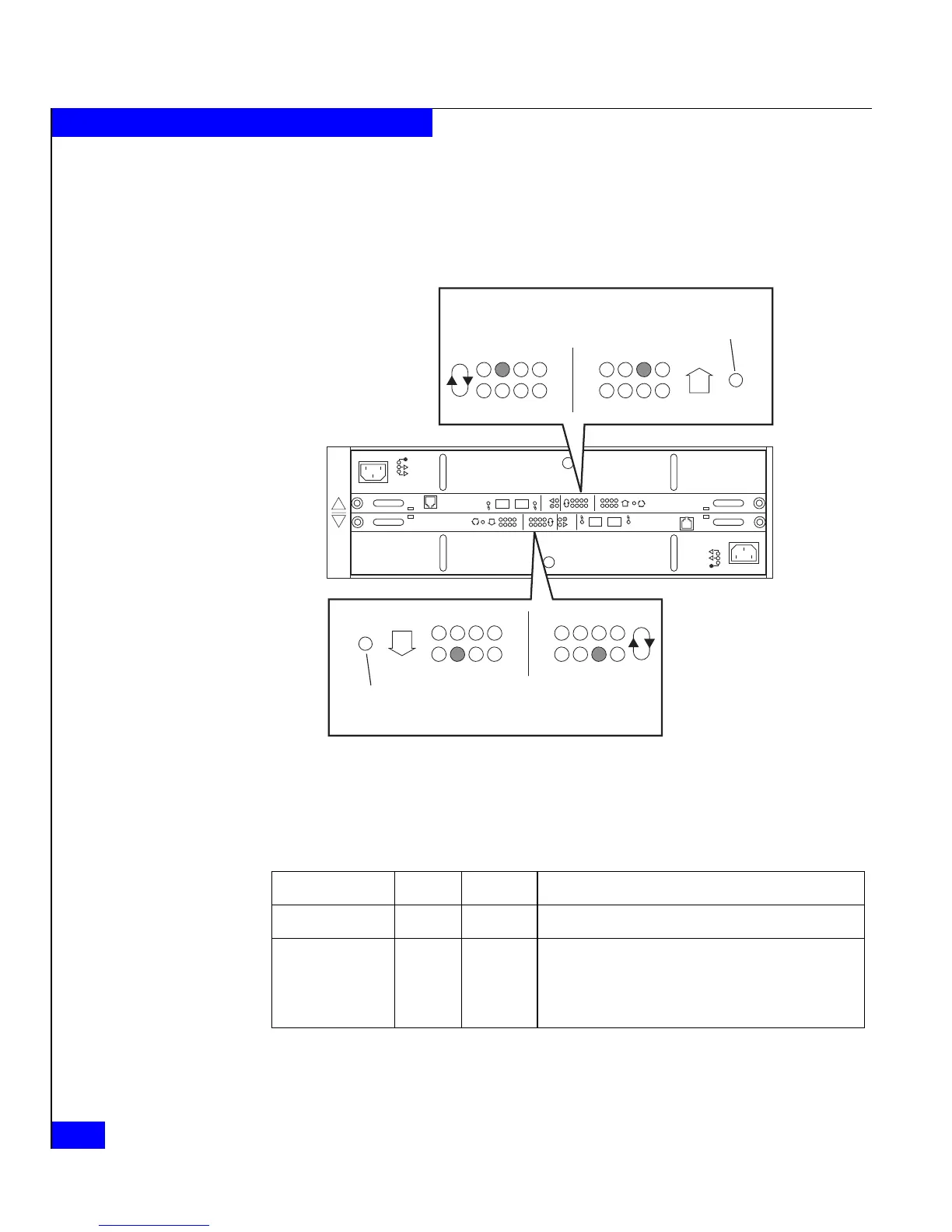
Figure 3-2 shows the enclosure address and bus ID indicators, visible
from the back of the enclosure. In this example, the DAE2P/DAE3P is
enclosure 2 on loop (bus) 1; note that the indicators for LCC A and
LCC B must always match.
Figure 3-2 Enclosure address and bus ID indicators
Table 3-2 describes the ID indicators.
Figure 3-3 shows the status LEDs for the power supply/system
cooling (power/cooling) modules.
!!
!!
!
EXP PRI
EXPPRI
#
!
EXP PRI
EXPPRI
#
A
B
0
1
2
3
4
5
6
7
0
1
2
3
4
5
6
7
Loop ID
Enclosure
Address
#
EA
Selection
0
1
2
3
4
5
6
7
0
1
2
3
4
5
6
7
Loop ID
Enclosure
Address
#
EA
Selection
EMC3178
Table 3-2 Enclosure and bus ID indicators
Light Quantity Color Meaning
Enclosure Address 8 Green Displayed number indicates Enclosure Address
bus ID 8 Blue Displayed number indicates bus ID
Blinking bus ID indicates invalid cabling; LCC A and
LCC B are not connected to the same bus or bus
maximum exceeded.
 Loading...