PACSystems™ RX3i and RSTi-EP CPU Reference Manual Section 6
GFK-2222AK October 2019
Serial I/O, SNP & RTU Protocols 173
▪ The number of registers value is two bytes in length. It must contain a value from 1
to 125 inclusive. The sum of the starting register value and the number of registers
value must be less than or equal to the highest register number available in the
attached CPU. The high order byte of the Starting Register Number and Number of
Registers fields is sent as the first byte in each of these fields. The low order byte is
the second byte in each of these fields.
6.3.3.3.3 Response:
The byte count is a binary number from 2 to 250 inclusive. It is the number of bytes in the
normal response following the byte count and preceding the error check. Note that the
byte count is equal to two times the number of registers returned in the response. A
maximum of 250 bytes (125) registers is set so that the entire response can fit into one
256-byte data block.
The registers are returned in the Data field in order of number with the lowest number
register in the first two bytes and the highest number register in the last two bytes of the
Data field. The number of the first register in the Data field is equal to the Starting
Register Number plus one. The high order byte is sent before the low order byte of each
register.
6.3.3.4 Message (04): Read Analog Inputs
6.3.3.4.1 Format:
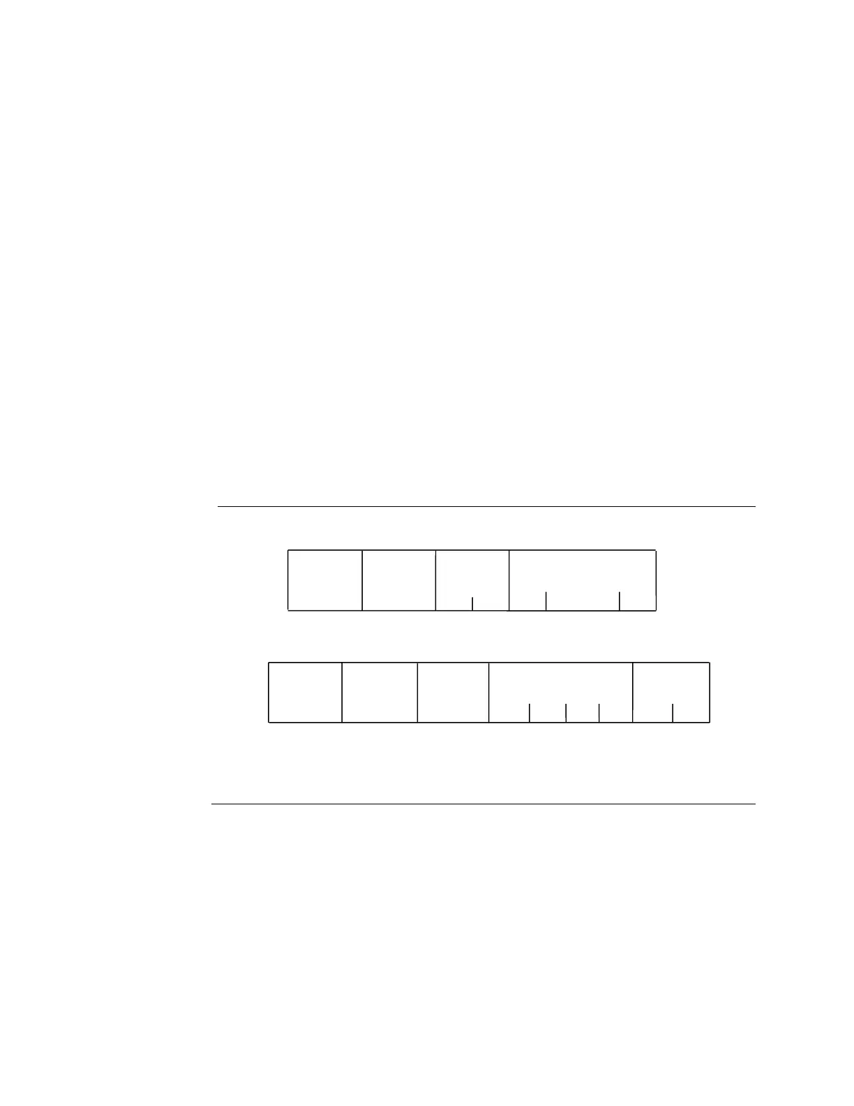
Figure 26: RTU Read Analog Inputs Message Format
6.3.3.4.2 Query:
▪ An Address of 0 is not allowed as this request cannot be a broadcast request.
▪ The function code is equal to 4.
▪ The Starting Analog Input Number is two bytes in length. The Starting Analog Input
Number may be any value less than the highest analog input number available in the
attached CPU. It is equal to one less than the number of the first analog input
returned in the normal response to this request.

 Loading...


