Emerson Process Management GmbH & Co. OHG 2-19
X-STREAM Non-Incendive
Instruction Manual
HASXENE-IM-EX
12/2014
2
Installation
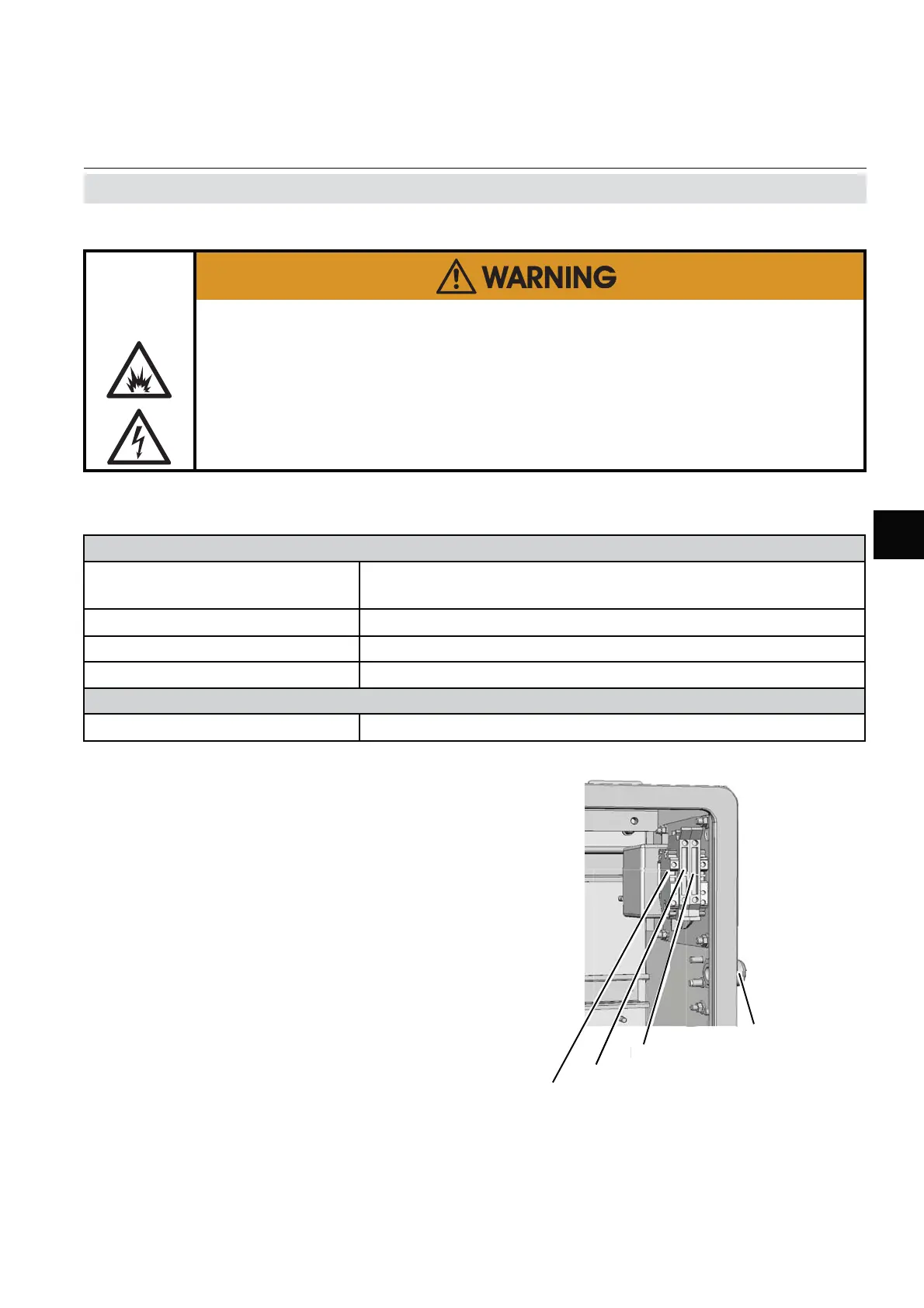
2.7 Installation - Electrical
• Feed the power cable through the upper-
most cable gland at the instrument´s right
side and strip the outer insulation.
• Strip the individual wires and connect to
the terminals (a label is located next to
the terminals on the mains fi lter housing).
• Finally, tighten the outer dome nut to se-
cure the power cable.
Fig. 2-10: Power Terminals
Live L
v
Earth PE
Neutral N
Power supply
cable gland
The power cord is connected to screw-type terminals located inside the housing.
Power Supply Terminals
Design, max. cross section
Screw type terminals with integral fues holders
max. 4 mm² (12 AWG)
Recommended cross section min. 1,5 mm² (15 AWG)
Skinning length: 8 mm (0.315"); no need to use wire end sleeves
Tightening torque: min. 0.5 Nm (4.4 in.lb)
Input Fuses
Specifi cation AC 230 V / T 6.3 A / 5x20 mm
EXPLOSION AND ELECTRICAL SHOCK HAZARD
All power and signal cables must end in a safe area or within a protective
enclosure (e.g. Ex e enclosure)!
Verify the power cord is layed with a distance of at least 1 cm (0.4 in) to any
signal cable to ensure proper insulation from signal circuits!

 Loading...


