Emerson Process Management GmbH & Co. OHG 2-9
X-STREAM Non-Incendive
Instruction Manual
HASXENE-IM-EX
12/2014
2
Installation
Gas connectors are accessible from the out-
side, on the underside of the instrument.
The number and confi guration of the gas in-
lets and outlets depends on the use, the unit
is to be put to, and is noted on a sticker on
the underside of the instrument next to the
connectors.
To simplify installation, we recommend label-
ling the gas lines in accordance with these
markings. This avoids confusion, should
the analyzer need to be disconnected for
maintenance.
Should it be necessary to open
the gas lines, the gas connectors should be
sealed with PVC caps, to prevent pollution by
moisture, dust, etc.
See fi gures 2-2 and 2-3 for an arrangement
of gas in- & outlets.
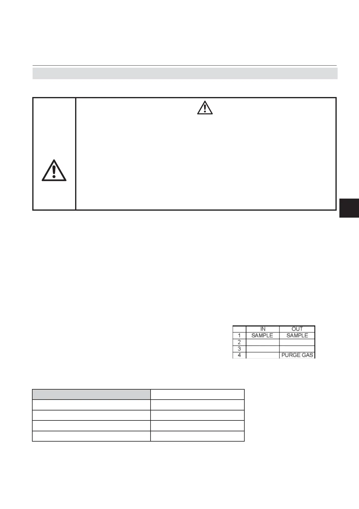
All connections are labeled (as shown in the
fi gure below):
Fig. 2-4: Labelling of Gas Connectors (example)
Gas connections
Gas connections
max number 8
max for purging (incl. / separate) 2 incl.
material Stainless steel
sizes 6/4 mm;
1
⁄4"
2.6 Installation - Gas Connections
TRACE OXYGEN MEASUREMENTS
The sensor for trace oxygen measurements is a consumable.
Remaining lifetime counts down when the sensor is in contact with oxygen.
For above reasons, the analyzer is shipped with the sensor as extra item in a
sealed bag! The sensor must be installed before analyzer startup, according
the instructions shipped with the sensor!
Do not use plastic tubing for trace oxygen measurements as it can permeate
oxygen from the ambient air and cause higher than expected oxygen
readings.
Note!
X-STREAM gas analyzers feature at maxi-
mum eight gas connectors. So, parallel tubing
is not possible for fi ve channel confi gurations
(at least two out of fi ve channels need to be
serial tubed)!

 Loading...


