EPSON
PRINTERS
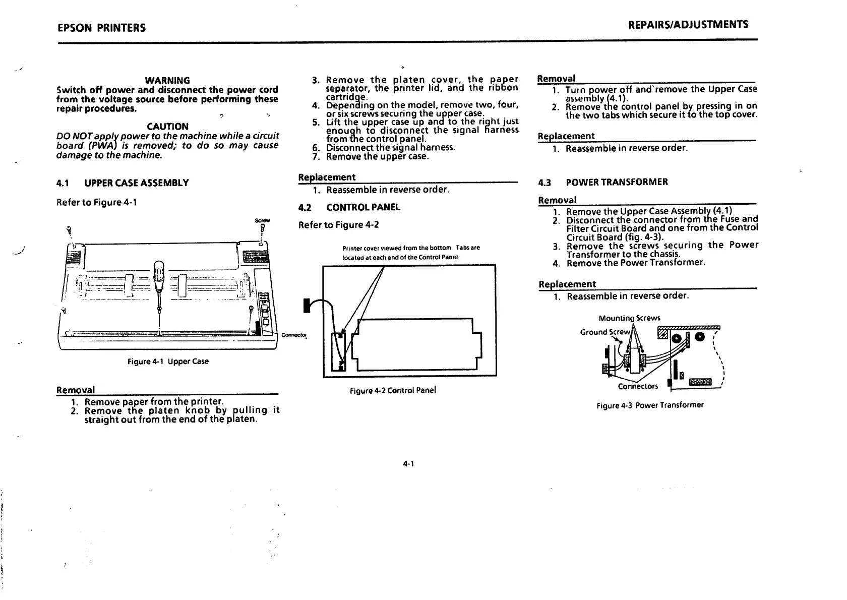
WARNING
Switch
off
power
and
disconnect
the
power
cord
from
the
voltage
source
before
performing
these
repair
procedures.
O
CAUTION
DO NOT
apply
power
to
the
machine
while
a circuit
board
(PWA) is
removed;
to
do
so
may
cause
damage
to
the
machine.
4.1
UPPER
CASE
ASSEMBLY
Refer
to
Figure
4-1
Figure
4-1
Uppercase
Removal
1. Remove
paper
from
the
printer.
2. Remove
the
platen knob by pulling it
straight
out
fromthe end of the platen.
3.
5.
Remove
the
platen
cover,
the
paper
separator,
the
printer
lid,
and
the
ribbon
cartridqe.
Depending on the model, removetwo, four,
or sixscrews securing
the
upper case.
Lift
the
upper
case up
and
to
the
right just
enough
to
disconnect
the
signal
harness
from {he control panel.
Disconnect
the
signal harness.
Remove
the
upper
case.
Replacement
1.
Reassemble
in
reverse
order.
4.2
CONTROL
PANEL
Refer
to
Figure
4-2
Printer
cover
viewed
from
the
bottom
Tabs
are
located
at
each
ertd
of
the
Control
Panel
Figure
4-2
Control
Panel
4-1
REPAIRS/ADJUSTMENTS
Removal
1. Turn
power
off
and'remove
the
Upper Case
assembly (4.1).
2. Remove
the
control
panel
by pressing in on
the
two
tabs
which
secure
it
to
the
top
cover.
Replacement
1.
Reassemble
in
reverse
order.
4.3
POWER
TRANSFORMER
Removal
Remove
the
Upper
Case
Assembly
(4.1)
Disconnect
the
connector
from
the
Fuse
and
Filter Circuit
Board
and
one
from
the
Control
Circuit Board (fig. 4-3).
Remove
the
screws
securing
the
Power
Transformer
to
the
chassis.
Remove
the
Power
Transformer.
Replacement
1.
Reassemble
in
reverse
order.
Mounting
Screws
Ground
Screw,
Connectors
Figure4-3 PowerTransformer
 Loading...