EPSON
PRINTERS
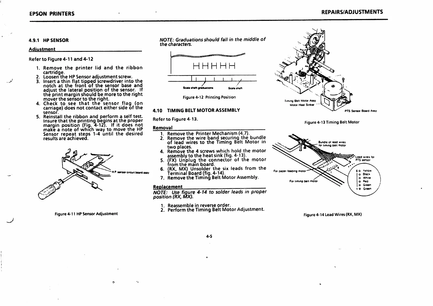
4.9.1
HP
SENSOR
Adjustment
Refer
to
Figure 4-11
and
4-12
1.
Remove
the
printer
lid
and
the
ribbon
cartridge.
2. Loosen
the
HP
Sensor
adjustment
screw.
3. Insert a thin flat tipped screwdriver into
the
notch
at
the
front
of
the
sensor
base
and
adjust
the
lateral position of
the
sensor. If
the
print margin
should
be
more
to
the
right
mover
the
sensor
to
the
right.
4.
Check
to
see
that
the
sensor
flag
(on
carriage)
does
not
contact
either
side of
the
sensor.
5. Reinstall
the
ribbon
and
perform
a
self
test.
Insurethat the printing beginsat the proper
margin position
(Fig.
4-12). If it
does
not
make
a
note
of
which
way
to
move
the
HP
Sensor repeat steps 1-4 until the desired
results
are
achieved.
HP.MniOfcircuitboird «mv
Figure 4-11 HPSensor Adjustment
NOTE:
Graduations
should
fall in
the
middle
of
the
characters.
HHH
HH
I I
ScM
e«*duation«
Figure 4-12 Printing Position
4.10
TIMING
BELT
MOTOR
ASSEMBLY
Refer
to
Figure
4-13.
Removal
1.
Remove
the
Printer
Mechanism
(4.7).
2. Remove
the
wire
band
securing
the
bundle
of
lead
wires
to
the
Timing Belt
Motor
in
two
places.
4.
Remove
the
4
screws
which
hold
the
motor
assemblyto
the
heat
sink (fig. 4-13).
5.
(FX)
Unplug
the connector of the motor
Trom
the
main
board.
6.
(RX,
MX)
Unsolder
the
six leads from
the
Terminal Board (fig. 4-14).
7. Remove
the
Timing Belt Motor Assembly.
Replacement
/
Sc«l«
th«fi
NOTE:
Use figure 4-14 to
solder
leads in
proper
position
(RX,
MX).
1.
Reassemble
in
reverse
order.
2. Perform
the
Timing Belt Motor Adjustment.
4-5
Timing Bell Motw Assy
Motw
Heal
Sinhaf
REPAIRS/ADJUSTMENTS
PTS
Sense
Boaid
Assy
Figure 4-13 Timing Belt
Motor
r
leading
I
iimmp
Bundle
iimmg
Lota
wiiet
loi
PTS
jsnjoi
veiiow
eiick
Wnue
o
Red
Gie«r
1 O
Gitan
Figure4-14 LeadWires
(RX,
MX)
 Loading...