REPAIRS/ADJUSTMENTS
4.16
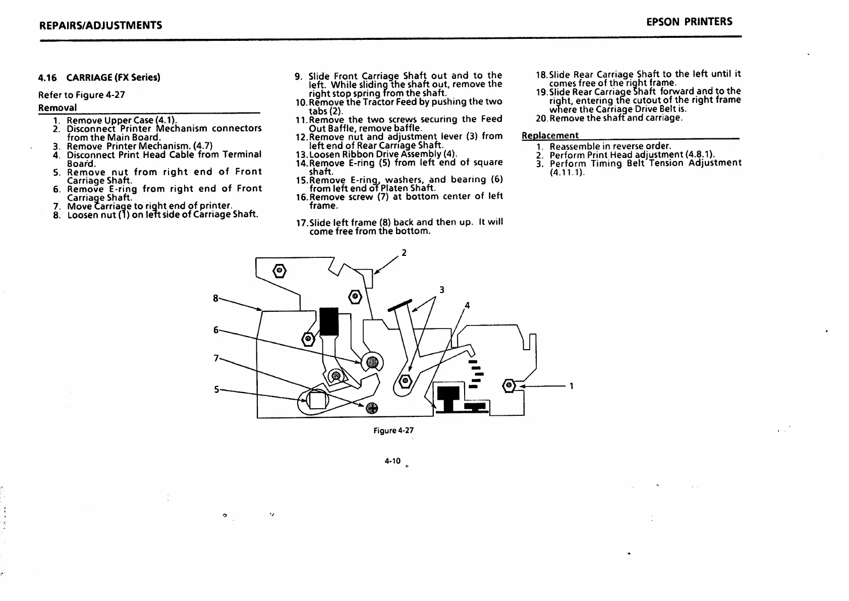
CARRIAGE(FX
Series)
Refer
to
Figure
4-27
Removal
1.
Remove
Upper
Case (4.1).
2.
Disconnect
Printer
Mechanism
connectors
from
the
Main
Board.
3.
Remove
Printer
Mechanism.
(4.7)
4.
Disconnect
Print
Head
Cable
from
Terminal
Board.
5.
Remove
nut
from
right
end
of
Front
Carriage
Shaft.
6.
Remove
E-ring
from
right
end
of
Front
Carriage
Shaft.
7. Movecarriage to right end of printer.
8. Loosen
nut
(i)
on
leftside
of
Carriage
Shaft.
9. Slide Front Carriage
Shaft
out
and
to
the
left.
While
slidinq
the
shaft
out.
remove
the
right stop springfromthe shaft.
10. Remove
the
Tractor
Feed by
pushing
the
two
tabs
(2).
11.
Remove
the
two
screws
securing
the
Feed
Out
Baffle,
remove
baffle.
12.Remove nut and adjustment lever
(3)
from
left
end
of Rear Carriage Shaft.
13.Loosen
Ribbon
Drive Assembly (4).
14.Remove E-ring (5) from left
end
of square
shaft.
15.Remove
E-rinq,
washers,
and
bearing
(6)
from
left
end
of
Platen
Shaft.
16.
Remove
screw
(7)
at
bottom
center
of
left
frame.
17.Slide
left
frame
(8)
back
and
then
up.
It will
come
free
from
the
bottom.
Figure 4-27
4-10
EPSON
PRINTERS
IS.SIide Rear Carriage Shaft to
the
left until it
comesfree of
the
right frame.
19.Slide Rear Carriage Shaft forward
and
to
the
right,
enteringthe cutoutofthe right
frame
where
the
Carriage
Drive Belt is.
20.
Remove
the
shaft
and
carriage.
Replacement
1.
Reassemble
in
reverse
order.
2. Perform Print Head adjustment (4.8.1).
3. Perform Timing Belt Tension
Adjustment
(4.11.1).
 Loading...