WIRING
DATA
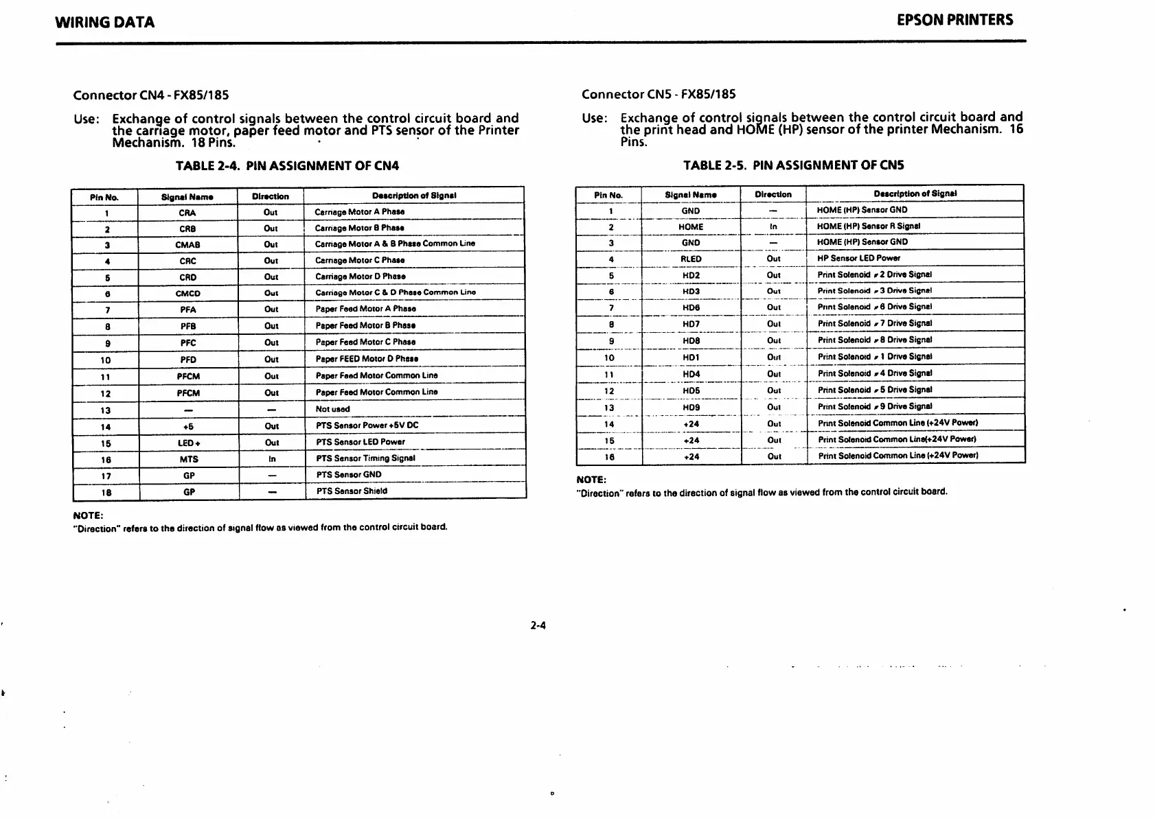
Connector
CN4
-
FX85/185
Use:
Exchange of control signals between
the
control circuit board and
the
carriage
motor,
paper
feed
motor
and
PTS
sensor
of
the
Printer
Mechanism.
18
Pins.
TABLE
2-4.
PIN
ASSIGNMENT
OF
CN4
PinNa
Signel
Name
Direction
Description
of
Signal
1
CRA
Out
Carriage Motor A
Phasa
2
CRB
Out
Carnsgo
Motor
B
Phasa
3
CMAB
Out
Carnage Motor A & 8
Phaso
Common
Line
4
CRC
Out
Camsga
Motor
C
Phasa
5
CRO
Out
Carriage
Motor
D
Phase
6
CMCD
Out
Carriage MotorC & 0
Phase
Common
Line
7
PFA
Out
Paper
Feed
Motor
A
Phase
8
PFB
Out
Paper
Feed
Motor
8
Phase
9
PFC
Out
Paper Feed Motor C
Phasa
10
PFD
Out
Paper FEEDMotor 0
Phase
11
PFCM
Out
Paper
Fasd
Motor
Common
Line
12
PFCM
Out
Paper
Feed
Motor
Common
Line
13
— —
Not
used
14
*6
Out
PTS
Sensor
Power
♦SV
DC
IS
LED-t-
Out
PTS
Sensor
LED
Power
16
MIS
In
PTS
Sensor
Timing
Signal
17
GP
—
PTS
Sensor
GND
18
GP
-
PTS
Sensor
Shield
NOTE:
"Direction" refers to the direction of signal flow as viewed from the control circuit board.
2-4
EPSON
PRINTERS
Connector
CN5
-
FX85/185
Use: Exchange of control siqnals
between
the
control circuit board
and
the
print
head
and
HOME
(HP)
sensor
of
the
printer
Mechanism. 16
Pins.
TABLE
2-5.
PIN
ASSIGNMENT
OF
CN5
Pin
No.
SIgnel
Neme
Direction
Description
of
Signal
1
GND
-
HOME (HP)
Sensor
GND
2
HOME
In
HOME (HP)
Senior
R
Signal
3
GNO
-
HOME
(HP)
Sensor
GND
4
RLED
Out
HP
Sensor
LEO
Power
5
H02
Out
Print
Solenoid
r 2 Drive
Signal
6
KD3
Out
Print
Solenoid
r3
Drive
Signal
7
HD6
Out
Pnnt
Solenoid
^6
Drive
Signal
8
HD7
Out
Print Solenoid # 7 DriveSignal
9
HD8
Out
Print
Solenoid
r 8 Drive
Signal
10
HD1
Out
Print Solenoid r 1 Drive Signal
11
HD4
Out
Print Solenoid
#4
Drive Signs!
12
HDS
Out
Print
Solenoid
<r
5 Drive Signal
13
H09
Out
Print
Solenoid
m9 Drive Signal
14
+24
Out
Pnnt
Solenoid
Common
Line
(+24V
Power)
15
+24
Out
Print
Solenoid
Common
Lina<+24V
Power)
16
♦24
Out
Print
Solenoid
Common
Line (•f24V
Power)
NOTE:
"Direction"
refers to the direction of signal flowas viewed from the control circuit board.
 Loading...