Appendix A-8 General Specifications Rev.B
Confidential
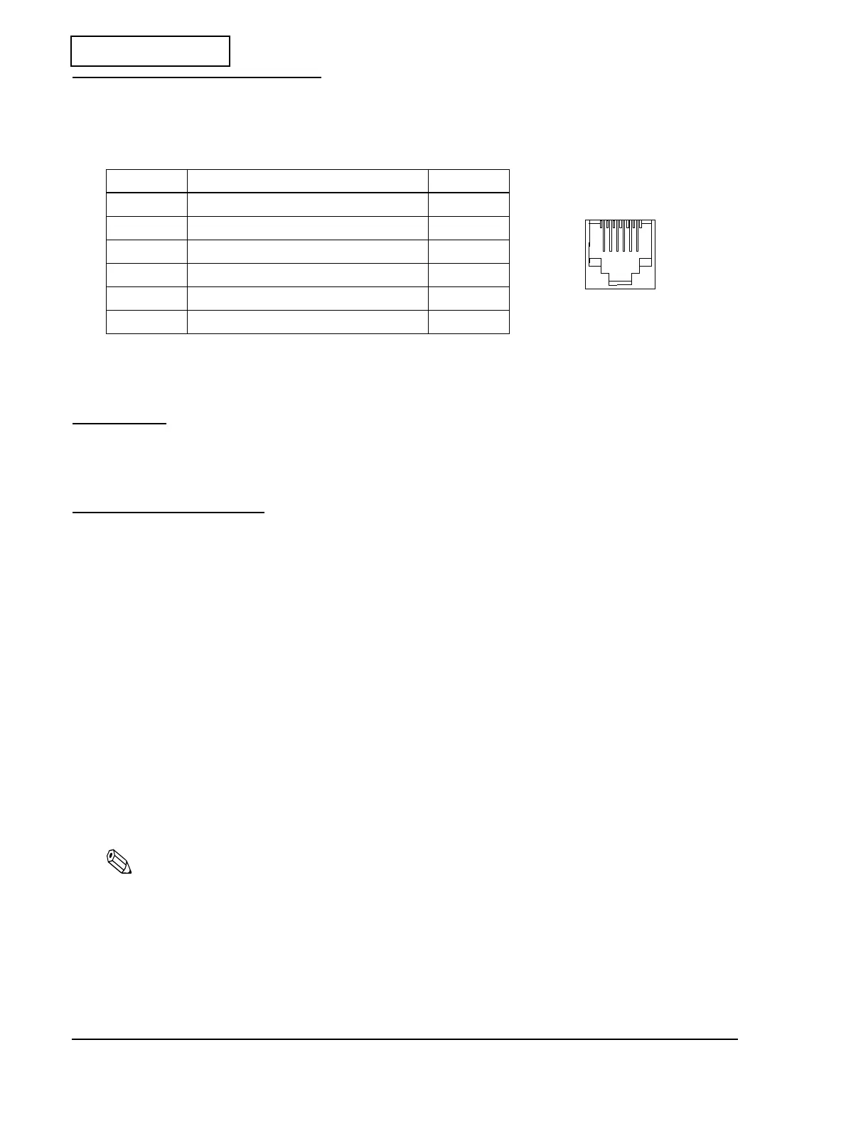
Drawer Kick-out Connector
Pin assignments
+24V is always output through pin 4 during power on.
Interfaces
Various interface boards (EPSON UB series, except for the UB-P02) can be used.
Buttons and Switches
Power switch
The power switch (non-locking, push switch) on the right part of the front face of the unit turns
the printer on or off.
You can use the DIP switches to enable or disable the power switch.
Panel Button
Feed (FEED) button:
Note:
The ESC c 5 command enables or disables the panel button. When disabled, the button will not function.
Table A-3 Drawer kick-out connector pin assignments
Pin Number Signal Name Direction
1Frame GND —
2 Drawer kick-out drive signal 1 Output
3 Drawer open/close signal Input
4 +24 V —
5 Drawer kick-out drive signal 2 Output
6 Signal GND —
Type: Non-locking push button
Function: Feeds paper. The paper cannot be fed if:
(1) roll paper end detector detects no paper.
(2) cover is open.
16
 Loading...