Appendix F-6 Overview of Electric Circuits Rev.B
Confidential
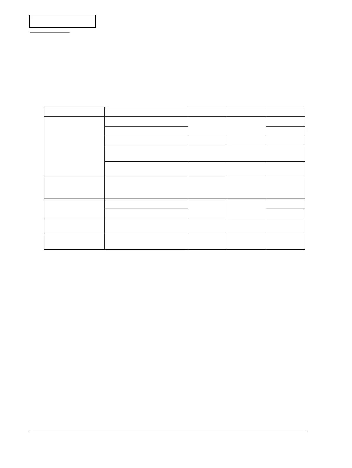
Test Points
Test points on the main circuit board
After a main circuit board unit failure, one basic method for diagnosing the cause of the problem
on the main circuit board unit is to check the power supply line. Use the following table to check
the power supply line. First, check step number 1, and proceed to the next step, if that is not the
problem.
Table F-5 Checking the power supply line
Power source Terminal name Test terminal Parts terminal Normal value
Power source for logic
circuit (DC)
Semiconductor switch ON — DS1, C 15V
Semiconductor switch OFF 24V
Power source for logic circuit (VIO) VIO UZ2, #4 5V
Power source for logic circuit
(VBUS)
VBUS UZ2, #5 3.3V
Power source for logic circuit
(GND)
GND — 0V
Power source for
mechanisms
+24V-operated components
(printer mechanism)
Drive power source (Q1, ON)
— Q1, D 24V
Paper feed motor Rotating REF_PF — 0.81~1.36V
Halted 0.0V
Power source for I/F
board
— — CN6, #5 24V
Power source for
drawer
— — UK1 pin#3 24V
 Loading...