Rev.B Overview of Electric Circuits Appendix F-5
TM-L90 Service Manual
Confidential
DIP switch on the main circuit board (DSW2)
This DIP switch is used only at the factory. Always set this to OFF.
Switch Circuit Board Assembly
The switch circuit board assembly consists of three LEDs, one switch, and one DIP switch.
Sub Circuit Board Assembly
The next table shows the major components of the sub circuit board and their major functions:
Interface Circuit Board Unit
The interface circuit board unit serves as the core of the system that controls data send and
receive operations between the TM-L90 and host computer. Various interface circuit boards can
be used (including the EPSON UB series, except for the UB-P02 and UB-S03).
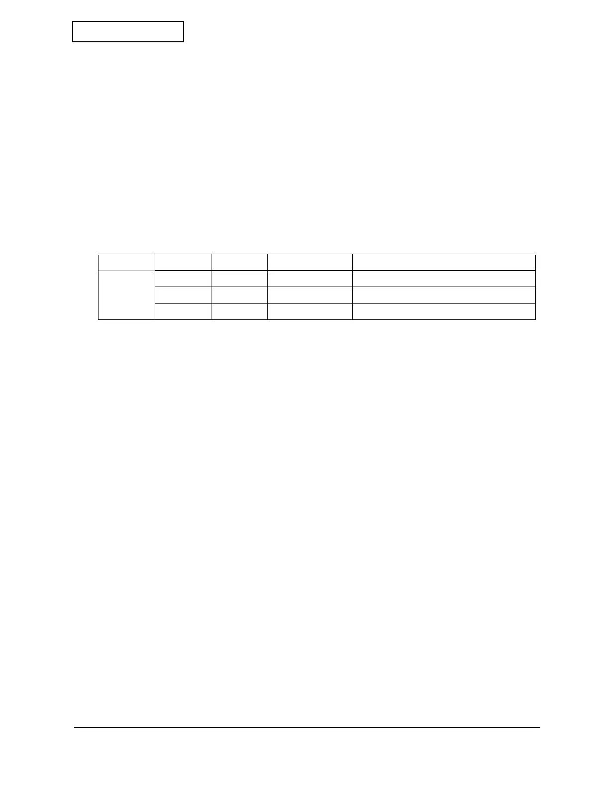
Table F-4 Major components of the sub circuit board unit and their major functions
Block Location Signal name Description Function
Connector CNS1 PS — Connector for PS adapter connection
CNS2 DKD — Connector for drawer connection
CNS3 — — Cable for main circuit board connection
 Loading...