E045 6 732786 - Rev.C
DL10
USB
RADIO 1
DL12DL11
RADIO 2
+/R1 F-/R2
BUS MON.
DL14
HIGH
VOLTAGE
AREA
BUS
DL15
SW3
SW1 SW2
8.8.
USB-A
2EASY
STOPLAMP OP-ACOMAC MAIN
W.L.
OP-BCLOPCOM
18171615
CLOP
2EASY
LOCK
RADIO 433-868
J5
PE N L
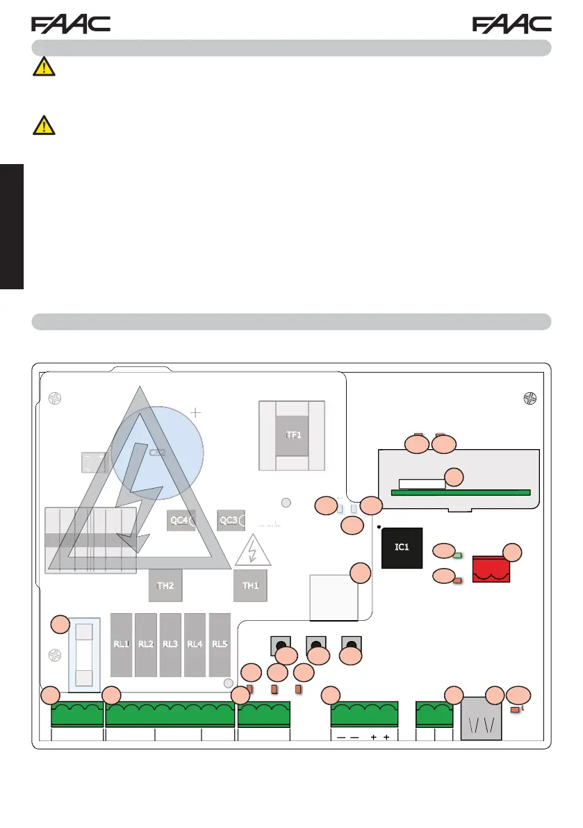
1 2 3 4 5 6 7 8 9 10 11 15 16 17 18 20 21
RL1 RL2 RL3 RL4 RL5
TH2 TH1
QC4 QC3
IC1
C52
TF1
F1
DB1
24V ERROR
DL13
DL17
DL16
5V
STOP
OP-B
OP-A
DL7
DL8
DL9
J1
J3
J9
J2 J11
FL1
2120111087M2M1 9654321LNPE
24V
I
H
V
LTAGE
REA
.
F
1
L1
L1
L1
FL1
F1
SW1 SW2 SW3
J1 J2 J3
J5
J8J9
J11
J10
DL7
DL10
DL11 DL12
DL13
DL14
DL15
DL16
DL17
LCD
DL8DL9
ENGLISH
3. BOARD LAYOUT
2. PREPARING FOR INSTALLATION
For safety reasons, it is important for people to carefully follow all the warnings and
instructions contained in this manual. Incorrect installation or incorrect use of the
product can cause serious harm to people. Before proceeding with product installation,
carefully read the entire manual. Keep these instructions for further reference.
Always cut off the electrical power before carrying out any work on the control unit
(connections, maintenance).
Always separate the power cables from the control and safety cables (button, receiver,
BUS-2EASY encoder, photocells, etc.). Avoid any electrical disturbance using separate
sheathing or a shielded cable (with shield connected to the earth).
• Ensure that upstream of the system there is a suitable magnetothermic differential switch with
omnipolar cut-off, as provided for in current safety regulations.
• Check for the presence of an adequate earthing system.
 Loading...