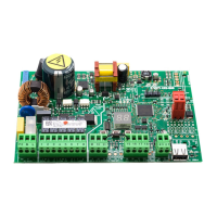
E045 8 732786 - Rev.C
MAX
500 mA
{
C1 C2
J11J3 J9J2
J1
15 16 17 18
20 219 10 11
PE N L
1 2 3 4 5 6 7 8
AC MAIN
PE N L M1123
W.L.
21
LOCK
20
LAMP
78
24V
3W
230V~
MAX 60W
Mot1 Mot2
COM OP CL
OP-A OP-B STOP
-
15
-
16
+
17
+
1891011
24V
M2456
COM OP CL
230V~ ±15%
50/60 Hz
12V~
24V
J1 J2 J3
J11
J9
*
*
ENGLISH
4. ELECTRICAL CONNECTIONS
4.1 J1 - PRIMARY MAINS POWER SUPPLY
PE Earthing Connection
For correct operation, you must con-
nect the switching power supply to the
system’s earthing conductor. Ensure
that upstream a suitable differential
magnetothermic switch has been in-
stalled.
N
Power Supply Connection
230 V~ ± 15% Neutral
L
Power Supply Connection
230 V~ ± 15% Line
Motor for SINGLE-LEAF or
FIRST LEAF during ope-
ning (closes for the second)
OPEN A
Total gate opening
(contact N.O.)
OPEN B
Partial gate opening
(contact N.O.)
STOP
Gate stop
(contact N.C.)
*
Blue or grey
Photocells and safety de-
vices: for connection, see
the related paragraph.
4.2 J2 - MOTORS AND FLASHING LAMP
1 M1 - COM Common contact motor 1
M1 = first leaf when opening or single leaf
M2 = second leaf when opening - CAN-
NOT be used for single leaf
To verify correct wiring and direction
of motor rotation, (see
6.4 TIME LEAR-
NING - SETUP
)
2 M1 - OP OP phase motor 1
3 M1 - CL CL phase motor 1
4 M2 - COM Common contact motor 2
5 M2 - OP OP phase motor 2
6 M2 - CL CL phase motor 2
7
LAMP Flashing lamp connection (MAX 60 W)
8

 Loading...