Home
FENDT
Tractor Accessories
varioguide
FENDT varioguide User Manual
5
of 1
of 1 rating
158 pages
Give review
Manual
Specs
To Next Page
To Next Page
To Previous Page
To Previous Page
Loading...
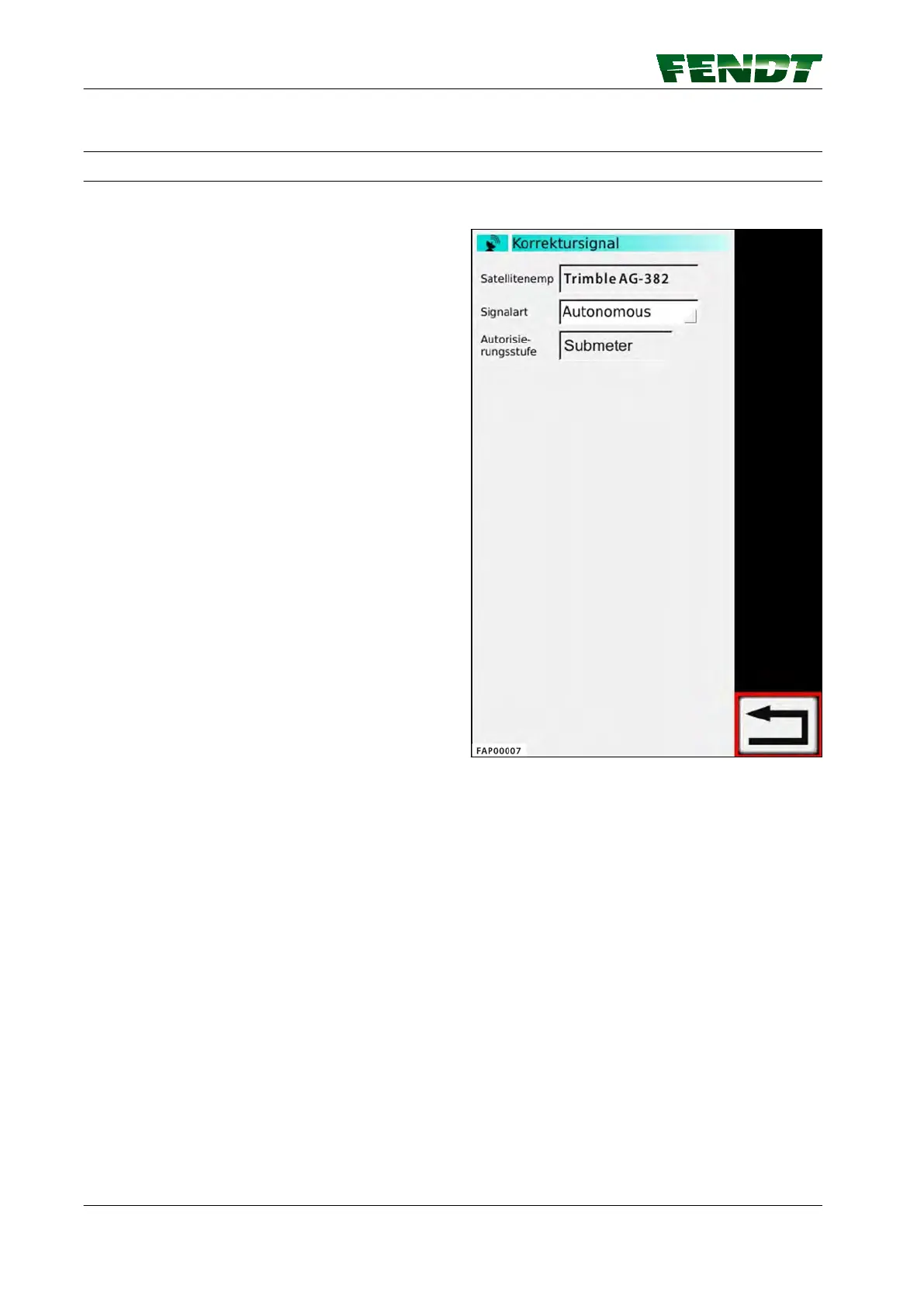
7.8 Submeter range with Trimble receiver
7.8.1 Autonomous
Autonomous Trimble AG-382
NOTE:
The position is determined without correction
signals, using only GPS and GLONASS satellites
(for regions in which there is no correction signal
or none can be received).
Fig. 48
7. Start-up
100
VarioGuide
438.020.070.012
99
101
Table of Contents
Default Chapter
7
Table of Contents
7
1 Introduction
11
Delivery of Varioguide System
13
OPERATOR'S MANUAL FENDT Varioguide
14
2 Safety Instructions
15
Safety and Accident Prevention Regulations
17
Marking of Places that Affect Your Safety
17
Advice for the Operator
17
Safe Operating Environment
18
Switching off in an Emergency Situation
18
3 Varioguide Definitions and Specifications
19
Definitions
21
GNSS and Correction Signal
21
Satellite Reception
21
Signal Interruption
23
Static and Dynamic Accuracy (Satellite Drift)
23
Convergence Time
23
Conditions of Use and Application Possibilities
23
Restrictions
23
Switch-Off Limits
24
Specification
25
Topcon Accuracy Specifications
25
Trimble Accuracy Specifications
25
4 Quick Start
27
Varioguide Menu Tree
29
Varioguide Info
31
Vario-Guide Main Menu
32
Implement Selection
34
Field Settings
36
Steering Behavior
38
Signal Settings
39
System Info
40
5 Map View
41
Overview
43
Map View Menu Tree
43
Map View
43
Display
45
Full Screen
45
Zoom
46
Info Bar
46
Steering Status
47
Novatel Bar Indicator, Trimble
47
Functions
49
Set Markers
49
Marker Settings
50
Worked Area Settings
50
6 Varioguide Components and Calibrations
53
Calibrations
55
Calibrate Steering Angle Sensor and Steering Valve
55
7 Start-Up
63
Load Implement
65
Caution
65
Load Implement Settings (7" Terminal)
65
Load Implement Settings (10.4" Terminal)
66
Create Implement
67
Call up Implement Settings on 7
67
Call up Implement Settings on 10.4
68
Front-Mounted Implement
69
Install Front-Mounted Implement
69
Determine the Working Width, Navigation Point Distance and Coupling
70
Length
70
Set the Working Width of the Front-Mounted Implement
71
Set the Navigation Point of the Front-Mounted Implement
72
Set the Coupling Length for the Front-Mounted Implement
73
Set the Center of the Front-Mounted Implement
74
Set the Trigger for the Front-Mounted Implement
75
Rear-Mounted Implement
76
Install Rear-Mounted Implement
76
Determine the Working Width, Navigation Point Distance and Coupling
77
Length
77
Set the Navigation Point of the Rear-Mounted Implement
78
Set the Coupling Length for the Rear-Mounted Implement
79
Set the Center of the Rear-Mounted Implement
80
Set the Trigger for the Rear-Mounted Implement
81
Save Mounted Implement Data
82
Save Implement on Stopping
82
Exchange Implement Data and Field Data
84
Plug in the USB Stick and Call up Data Exchange
84
Insert USB Stick
84
Call up Data Exchange on 10.4
84
Transfer Implement Data and Field Data to the USB Stick
85
Select and Transfer All Data
86
Transfer Implement and Field Data from the USB Stick to the Terminal
87
Select and Transfer All Data
89
Correction Signals
90
Overview of Correction Signals Depending on the Receiver
90
Submeter Range with Novatel Receiver
91
Autonomous
91
Egnos / Waas
92
Centimeter Range with Novatel Receiver
93
FENDT Base Station
93
Configure the FENDT Base Station Correction Signal
93
Fallback: FENDT Base Station
94
External Station
95
Configure the External Station Correction Signal
95
External Fallback Station
96
RTK Network (Internal Mobile Radio Modem)
96
Configure the Internal Mobile Modem Correction Signal
96
Activate/Deactivate Internal Mobile Modem Fallback
98
RTK Network (External Mobile Radio Modem)
98
Configure the External Mobile Modem Correction Signal
98
Submeter Range with Trimble Receiver
100
Autonomous
100
Egnos / Waas
101
Rangepoint RTX
102
Decimeter Range with Trimble Receiver
103
Centerpoint RTX Satellite
103
Set Correction Signal for Centerpoint RTX Satellite
103
Fallback for Centerpoint RTX Satellite
104
Centimeter Range with Trimble Receiver
105
FENDT Base Station
105
Configure the FENDT Base Station Correction Signal - Trimble AG-715 450 Mhz Radio Modem
105
Configure the FENDT Base Station Correction Signal (Trimble 900 Mhz)
106
RTK Network (Internal GSM/GPRS Modem)
107
Configure the Internal Mobile Modem Correction Signal (GSM/GPRS)
107
RTK Network (External Mobile Radio Modem)
108
Configure the External Mobile Modem Correction Signal
108
Trimble Receiver Settings
109
Xfill Settings
109
Field Settings
111
Add Field
111
Record Field Boundary
112
Record/Manage Obstacles
115
Way-Line
119
Create and Save Way Line
119
Path to Path Distance
124
Check System
125
Check System Info/System Status
125
Activate Varioguide System
127
Switch on Automatic Way Line Guidance
127
Adjust Way Line
128
Way Line Offset
128
Headland Settings
129
Headland Management Ti/Autoti
131
Operation with the Base Station
133
Brief Description
133
Scope of Delivery and Accessories
133
LED and Keys on the Base Station
136
Initial Start-Up
137
Operating Modes
138
Start-Up
138
Set the Base Station Channel on the Tractor
139
Operate Base Station with External Battery
141
8 Faults and Remedy
143
Fault Diagnostics
145
Problems and Possible Remedial Action
145
9 Appendix
149
Glossary
151
5
Based on 1 rating
Ask a question
Give review
Questions and Answers:
Need help?
Do you have a question about the FENDT varioguide and is the answer not in the manual?
Ask a question
FENDT varioguide Specifications
General
Brand
FENDT
Model
varioguide
Category
Tractor Accessories
Language
English
 Loading...