3.
Assign a name and press to confirm.
Fig. 11
7.2.3.2 Determine the working width, navigation point distance and coupling length
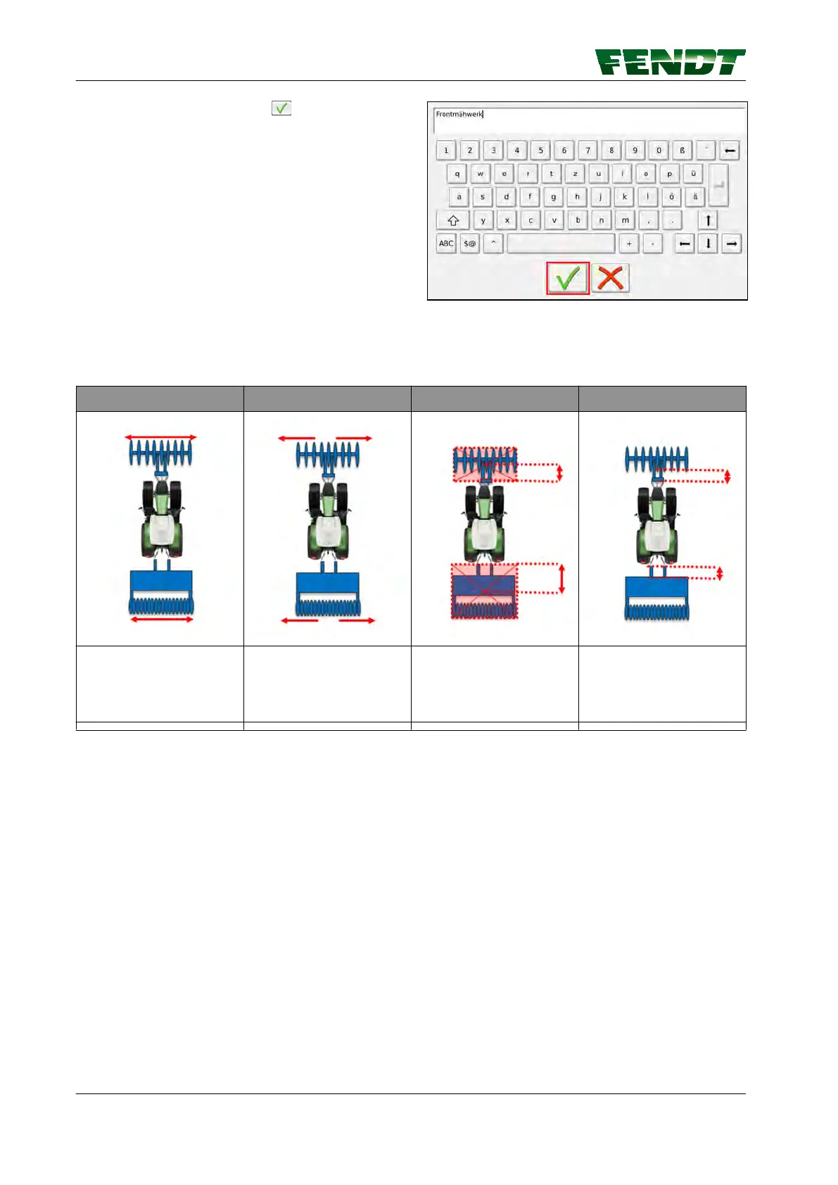
Working width Center Navigation point Coupling length
Actual working width of
the implement
Movement of the
implement from the
center (e.g. for mowers)
Distance of the
horizontal rotational axis
of the implement from
the lower link hooks
Distance of the
processing area of the
implement from the
lower link hooks
Procedure
1.
Start work and drive approx. 10 m.
2.
Measure the processed width (working width).
3.
Measure the length between the navigation point of the implement and the attachment hook
NOTE:
The navigation point is the point on the implement that follows the wayline.
4.
Measure the length between the start of the processed area and the attachment hook of the front
power lift
NOTE: If the mark is to be created at the end of the implement, measure from this point to the end
of the implement.
7. Start-up
70 VarioGuide
438.020.070.012
 Loading...