10.2 Basic informations
CPU
Slot 2
Slot 1
PWD CLR
RCVR
1 2
external connectors
LAN 1
LAN 1
Management
LAN
VGA
Shared LAN 2
Gen 2
DIMM 2A
DIMM 1A
DIMM 2B
DIMM 1B
Micro
SD
FAN1
FAN2
SSD2
M.2
M.2
SSD1
Battery
TPM
FAN3
FAN4
iRMC
S5
JP8
HDD LED
ROC
PWR4
INDICATE
CSS
SATA
ODD
Front VGA
OOB
Intel
i210
Service
LAN
USB 1
SATA
0-3
SERIAL
Intel
C246
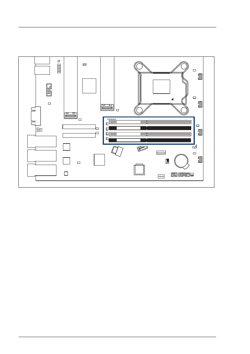
Figure 146: Slots of the main memory
The system board is equipped with four memory slots.
Memory sequence
–
Populate memory slot 1 / channel A (DIMM 1A) first.
–
Within all channels, memory slot 1 must be populated prior to slot 2.
–
If memory modules with dif
ferent capacities are used:
–
Install modules with higher capacities first.
– Within a channel, install modules in descending order of capacity.
–
If memory modules with different speeds are used, the lowest clock rate
applies for all DIMMs.
Main memory
234 Upgrade and Maintenance Manual RX1330 M4
 Loading...