EasyManua.ls Logo

Furuno 2127 User Manual

Furuno 2127
136 pages
To Next Page IconTo Next Page
To Previous Page IconTo Previous Page
Page #14 background imageLoading...
Page #14 background image
1. MOUNTING
1-6
1.2 Monitor Unit
The monitor unit can be flush mounted in a console panel, or mounted on a desktop using
the optional accessories. For MU-190/231, see the applicable Operator’s Manual(s).
Note: FAR-2117-BB/2127-BB have no monitor unit. Prepare a suitable monitor locally.
Recommended monitor: SXGA (1280x1024), aspect ratio 5:4
Mounting considerations
When selecting a mounting location, keep in mind the following points:
Select a location where the display unit can be viewed conveniently and where the
screen can be viewed while facing towards the bow.
The optimal viewing distances for the radar display units are: MU-170C: 920 mm,
MU-201CR: 1080 mm, MU-231CR: 1200 mm. Select a suitable mounting location
considering the applicable distance.
Locate the unit out of direct sunlight and away from heat sources because of heat that
can build up inside the cabinet.
Locate the equipment away from places subject to water splash and rain.
Leave sufficient space on the sides and rear of the unit to facilitate maintenance.
A magnetic compass will be affected if the monitor unit is placed too close to the magnetic
compass. Observe the compass safe distances on page ii to prevent deviation of a
magnetic compass.
Mounting procedure
Flush mounting
Follow the procedure below to mount the monitor unit in a console panel.
1. Make cutout in mounting location referring to the outline drawing shown below.
2. Insert the monitor unit to the hole and fix it with four tapping screws (6x30).
3. Attach panel hooks near the fixing holes (upper part). See next page. These are used to
pull out the monitor unit from a console panel for servicing.
4. Attach four panel covers to the fixing holes.
(79)
454
506
534
4-φ8
FIXING HOLES
Monitor unit MU-201CR
490
420
4-FIXING HOLES
30
80
506±1
296±1
(For FAR-2117/2127)
±1
296±1

Table of Contents

Question and Answer IconNeed help?

Do you have a question about the Furuno 2127 and is the answer not in the manual?

Furuno 2127 Specifications

General IconGeneral
BrandFuruno
Model2127
CategoryMarine Radar
LanguageEnglish

Summary

SAFETY INSTRUCTIONS

General Safety Warnings

Covers DANGER, WARNING, and general safety advice.

Electrical Safety Precautions

Specific warnings and precautions related to electrical safety.

EQUIPMENT LISTS

Standard Supply

Lists the components included in the standard equipment package.

Optional Equipment

Lists optional equipment that can be added to the system.

SYSTEM CONFIGURATION

System Diagram

Visual representation of the overall system setup and connections.

MOUNTING

Mounting Considerations

General guidelines for selecting mounting locations and ensuring optimal performance.

Antenna Unit Mounting

Detailed steps for assembling and mounting the antenna unit.

Monitor Unit Mounting

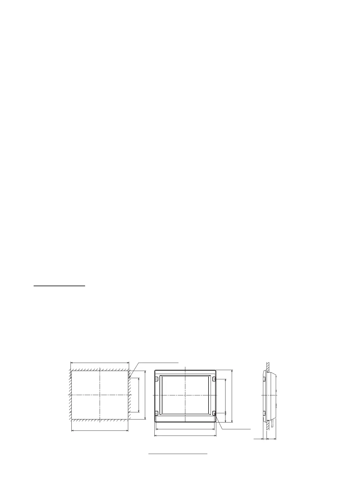
Procedures for flush and desktop mounting of the monitor unit.

Control Unit Mounting

Procedures for mounting the control unit, including flush and desktop options.

Processor Unit Mounting

Procedures for mounting the processor unit, including floor and bulkhead mounting.

WIRING

Wiring Considerations

General advice on cable routing to minimize electrical interference.

Interconnection Diagram

Diagram illustrating the connections between all system units.

Antenna Unit Wiring

Detailed steps for wiring the antenna unit.

Monitor Unit Wiring

Procedures for fabricating and connecting power cables to the monitor unit.

Processor Unit Wiring

Procedures for connecting various cables to the processor unit.

Changing AC Power Specification

Steps to change the processor unit's AC power specification between 100-240 VAC.

SETTING AND ADJUSTMENT

DIP Switch Setting

How to set the DIP switches on the processor unit for different configurations.

Initializing Tuning

Procedure for performing automatic tuning of the radar.

Heading Alignment

Process to align the radar heading with the vessel's bow.

Adjustment Sweep Timing

Adjusting sweep timing for accurate target display and range.

Suppressing Main Bang

Method for reducing or eliminating main bang interference.

Scanner Setting

Configuration of scanner parameters like blind sectors and antenna revolution.

INSTALLATION Menu Settings

Accessing and configuring installation parameters via the menu.

OWN SHIP INFO Menu Setting

Inputting own ship's dimensions and antenna position.

TT PRESET Menu Setting

Setting up target tracking (TT) presets for efficient operation.

Dual Radar Display

Enabling and configuring the dual radar display feature.

INSTALLING OPTIONAL EQUIPMENT

Gyro Converter GC-10 Installation

Steps to install the Gyro Converter GC-10 board inside the processor unit.

Memory Card Interface Unit Installation

Procedures for mounting and connecting the Memory Card Interface Unit.

DVI-RGB Conversion Kit Installation

Steps for installing the DVI-RGB Conversion Kit for VDR connection.

Performance Monitor PM-31 Installation

Instructions for installing the Performance Monitor PM-31 in the antenna unit.

Junction Box Installation

Guidelines for mounting and connecting the Junction Box.

INPUT/OUTPUT DATA

Input Data Specifications

Details of input data signals like Heading, Speed, and Navaid data.

Output Data Specifications

Details of output data signals like Radar system data and TT data.

Related product manuals