EasyManuals Logo

Furuno 2127 User Manual

Furuno 2127
136 pages
To Next Page IconTo Next Page
To Previous Page IconTo Previous Page
Page #62 background imageLoading...
Page #62 background image
4. INSTALLING OPTIONAL EQUIPMENT
4-2
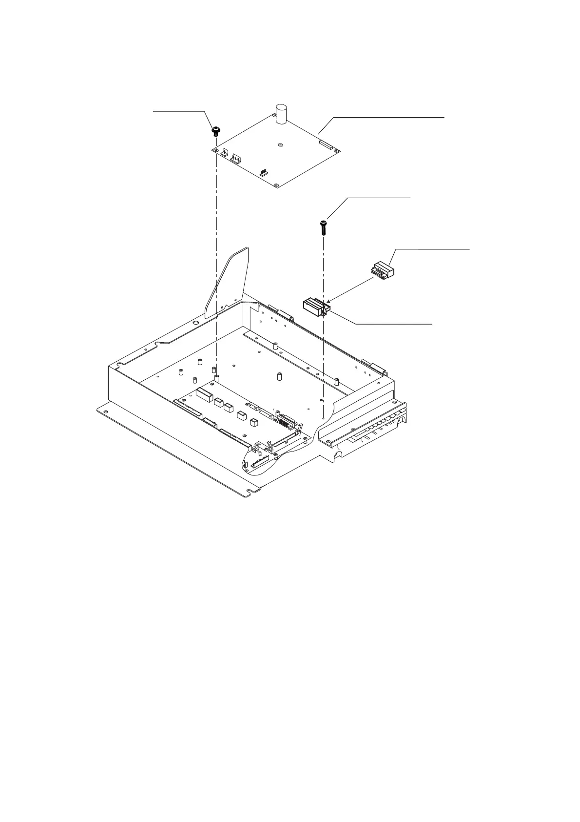
2. Fasten the GYRO CONVERTER board in the processor unit with five washer head
screws and male connector 231-607/019-FUR (called J602) with two screws.
Connector (231)
231-607/019-FUR
1
7
Connector (231)
231-107/026-FUR
11
77
GYRO CONVERTER board
64P1106A
Screw
M3x8 5 pcs
Screw
M2.6x10 2 pcs
Attaching GYRO CONVERTER board in the processor unit
3. Connect the GYRO CONVERTER board and the 03P9342 board with connector
assemblies 03-2088 and 03-2091.

Table of Contents

Questions and Answers:

Question and Answer IconNeed help?

Do you have a question about the Furuno 2127 and is the answer not in the manual?

Furuno 2127 Specifications

General IconGeneral
BrandFuruno
Model2127
CategoryMarine Radar
LanguageEnglish

Related product manuals